| Item | Parameters |
| Applied standard | GB 16808-2008 |
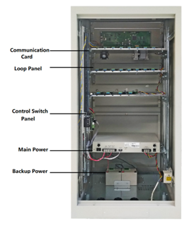
| Main power | AC220V (187V~280V)50Hz±1Hz |
| Backup power | DC24V |
| Power consumption | ≤48W (of the control panel itself) |
| Working environment | -10℃~55℃, ≤93%RH |
| Wiring | Two-wire, polarity-free |
| Transmission distance | ≤1500m |
| Capacity | 20 loops, 200 points (detector, module, power cabinet) each loop |
| Connecting equipment | Detectors, sounder beacons, modules by two-wire bus communication |
| Relay outputs | 2 sets of fire relay
Contacts capacity: 2A/DC30Vor 1A/AC125V |
| Alarm method | Sound and light alarm |
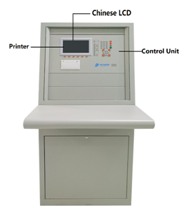
| Display method | 7” LCD |
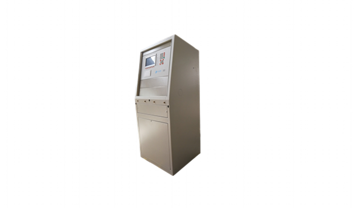
| Dimensions | Cabinet type (L×W×H): 545mm ×800mm ×1245mm |
| Weight | 60kg |