JTY-H-JBF4382 Infrared Beam Detector (hereinafter referred to as detector) is a reflective bus addressable linear beam smoke detector, suitable for our 11SF, 51S series control panel. Its relays output fire and fault signals, which can connect fire alarm control panels of different manufacturers. The detector is equipped with laser module and LED signal indication. The whole debugging process is fast and easy.
Product Features
• Reflective linear beam smoke detector that is an integrated design of transmitting and receiving ends.
• Switch signal output, compatible with signal input module of any manufacturer.
• Easy debugging. The laser module quickly locate the installation position of the reflector. The LED indicating the signal strength.
• Automatic gain control technology. Automatic compensation of background signal and strong resistance to light;
• Embedded microprocessor, full function self-diagnosis, and disturbance automatic filter technology.
• Two sets of independent precision fine tuning provide accurate calibration. horizontal/vertical angle optical adjustment is convenient.Technical Data
Power supply: DC18V~DC30V
Monitoring state: ≤15mA
Alarm state: ≤35mA
Fault state: ≤25mA
Debugging state: ≤25mA
Beam decreasing rate
First rate: 30%
Second rate: 40%
Third rate: 50%
Forth rate: 60%
Relays
Max voltage: DC30V
Max current: 2A
Optical path distance: 5m—100m
Max protection area: 1400㎡
Adjust angle: 1 degree
Standard applied: GB 14003-2005 “Smoke Detector – Line Detectors Using an Optical Light Beam”
Indicating state
Monitoring state: red indicator flashes
Alarm state: red indicator is constant on
Fault state: yellow indicator is constant on
Debugging state: green indicator flashes or constant on
Dimensions:185 mm× 115mm×126mm(L×W×H)
Weight: 564gOperating temperature: -10—+50℃Relative Humidity: ≤93%RH (40±2℃)Structure and Installation Dimensions (mm)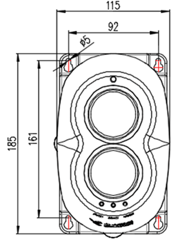

When the detector is connected to the loop of the panel, it needs to set the address (range 1~200) by the encoder.
When installing the detector, it should avoid direct sunlight, halogen light and other strong light sources shining on the receiver, and ensure that the angle between the interference light source path and the detector light path is greater than 5°.
Install the reflector on the other side of the protection area. The position of installation can be determined by the laser module of the detector. When positioning, adjust the horizontal and vertical rotary knob of the detector to make the laser module as perpendicular to the mounting surface as possible.
When the installation distance is between 5m and 50m, two reflectors should be used. When the installation distance is between 50m and 100m, 4 reflectors need to be used. When used in combination, the reflectors should be tightly arranged and no gap should be left between the reflectors.
Installation dimensions and diagram of reflectors
A. Single reflector:
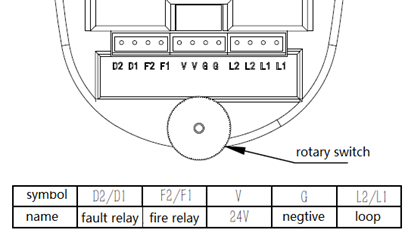
A. when used with Beida Jade Bird control panel, it is necessary to connect the DC 24V power cable to the terminal of "V, G", and "L1 and L2" to the loop (non-polar).
B. When connecting with alarm system of other manufacturers, connect the DC 24V power cable to the terminal of "V and G". "D1 and D2" are fault passive output contacts, and "F1 and F2" are fire passive output contacts.
Diagram of terminal is as follows• Regular maintenance and calibration
• Conduct activation test every six months recommended.


.jpg)
.jpg)