Tel:400 008 9119 Login  CN | EN

JBF6189-D

Two-wire, non-polar, AC220V/DC24V, two power supply modes, connected to up to 4 sensors, with LCD, visual and acoustic alarm function and keypad.
Combined Electrical Fire Detector


JBF6189-D is a 4-loop combined electrical fire monitoring detector.It connects with JBF-61S30,JBF-61S30-H electrical fire monitoring equipment of Jade Bird Fire by two-Dire polarity-free cable. When the residual current or the temperature of the protected cable reaches its alarm threshold, the detector gives out alarm signal within 30 seconds, which keeps electricity safety and prevents fire occurrence. The JBF6189-D combined electrical fire monitoring detector is widely used in power supply units in warehouse with dangerous materials, high-rise buildings, public places and residential buildings.
 
Product Features
•  Can be independently used without monitoring equipment in small business sites.
​•  The detector can connect 4 loops of sensors. The type of sensors can be residual current transformer, temperature sensor and current transformer based on the field needs.
​•  The detector is equipped with a LCD screen and operative buttons, and can give out visual and sound alarm. The detector views and sets sensor type, alarm threshold, and address of connected sensors on each loop, and checks online status and real-time detected value of all connected residual current transformers, temperature sensors and current transformers. The detector can also perform self-test.
​•  Occupies 1 address on the loop.
​•  The detector has alarm relays and fault relays that output status when external equipment are connected.
​•  Supports folded installation and rail installation.
​•  Communication expansion ports are reserved.
​•  Maximum communication distance:1500m.

Technical Data

ItemTechnical parameters
Object monitoredTemperature, residual current, current;
Alarm thresholdResidual current: 200mA~1000mA(settable) Step: 1mA; Temperature: 55℃~140℃(settable) Step: 1mA; Current 5A~1000A, Step: 1A
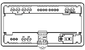
WiringL1 & L2 for loop connection - polarity-free;
Communication distance1500m
Sensor loop length≤3m
Power supplyAC 220V 50 Hz / DC24V
Operating current<10mA
Power<2W
InstallationFolded installation, 35mm rail mounting;
Applied environmentTemperature: -10℃~40℃
Humidity: 10%~93%(non-condensation)
 
Structure and Dimensions
 

JBF6189 series detectors are installed in two ways, folded installation and rail installation:
​•  Infolded installation: first remove the retention clips on both sides of the detector, mount the detector to the cabinet door, and then reinstall the retention clip to both sides of the detector to ensure that the detector is securely mounted on the cabinet door. Finally, wire the sensor signal loop, communication line, power cord and others to the detector.
​•  In rail installation: first connect the sensor signal loop, communication line, and power cord to the detector, and then install the detector to the 35mm standard rail. 

Wiring
 
•  L, N: power wiring terminals (AC 220V, 50Hz/DC24V). Remove the screws of the protective bezel when wiring, and after the wiring is finished, reinstall the protective bezel. Tighten the screws to prevent electric shock.
​•  1~4: detector sensor terminals. Each number includes 2 terminals. The 1~4 correspond to the 1~4 monitored loops respectively.
​•  L1, L2: bus loop terminals, L1 and L2 each includes 2 terminals, providing better wiring when the detector is used in network and needs more wiring.
​•  FIRE: alarm relay output, usually open, close under alarm condition.
​•  FAULT: fault relay output, usually open, close under fault condition. 

Precautions
•  Strong and weak cables should be separated, and no crossof wires is allowed. It is strictly forbidden to lay the loop in the same metal tube with power lines, lighting lines, video lines, broadcast lines, or telephone lines, etc. Wiring should be neat, and wires should be tied into bundles. Fire retardant PVC pipe, metal pipe and metallic channel can be used for cabling. If used, the opening should be sealed after cabling is finished.
​•  The communication line between the monitoring equipment and the detector should be twisted pair. Suggested wire diameter should not be less than 1.5mm2. When the system is applied in place with strong interference, the communication line should use shielded twisted pair. The shield should be well grounded. Otherwise the shielding layer won’t have effects. The cable connecting sensor and detector should adopts twisted pair. Its cross section no less than 1.0mm2 and its length no more than 3m. 
•  This product should be installed in dry environment and firmly installed. Regular inspection should be conducted.
​•  When install residual current transformer, ensure that the detected power cable (or copper bar) all pass through the transformer through the hole. Equipotential line (or grounding line) cannot pass through the hole. The connection between the residual current transformer and the detector does not allow open circuit. The temperature sensor and the cable must be in a good insulating state.
​•  The installation of the detector should conform to the environmental conditions applicable to the product design itself, as well as to the requirements of the construction specifications.
​•  In order to ensure line reliability, do not use single core cable or non-twisted cable for the loop.
​•  It is prohibited to wire when the device is powered on. 
•  The loop should adopt ZR-RVS-2 x 1.5mm2. When laying the cable, make sure to separate them from the strong electrical cables.
​•  When the communication cable is of shielded twisted pair, the shielding must be well grounded.
​•  The temperature sensor and the cable must be in good insulation.

​•  Do not use single core cable or non-twisted cable for the loop.