DESCRIPTIONThe FW963AR/FW963AW Horn Strobes, FW973AR/FW973AW, and W983AR/FW983AW Strobes are a family of addressable multi-candela visual and audible signal appliances with light sources generated from white LED, listed according to UL 1971, UL 1638, UL 464, ULC-S525 and ULC-S526 for indoor use. The LED light source offers superior performance, including low power consumption and long operating life. Each appliance has the intelligence to report its location (the device address) and status to FireWathcer series fire alarm control panels. Six levels of light output are selectable. Figure 1 shows relative light outputs in horizontal and vertical dispersion from strobes mounted on walls/ceilings.
The strobe appliances produce a flash rate of one flash per second over the Regulated Voltage Range. The temporal tone generated by the horn portion is designed as per ANSI and NFPA72 for standard emergency evacuation signaling requirement.
The appliance has the feature that can synchronize multiple horn and/or strobes based on loop.
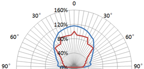
---- UL Limit (percent)---- appliance intensity (percent)
Figure 1. Horizontal and Vertical Light Outputs
ATTENTION
The product must be used within its published specifications and properly installed, operated, and maintained, in accordance with these instructions. Users are solely responsible for determining whether a product is suitable for the user’s purposes or achieves the intended results. Read the instructions carefully before using this product. Failure to comply with any of the instructions, cautions, and warnings could result in improper application, installation and/or operation of these products in an emergency situation. This could result in property damage and serious personal injury or death.
NOTE
Do not paint this device.
Any material extrapolated from this document or from Maple Armor’s instructions or other documents describing the product for use in promotional or advertising claims, or for any other use, including description of the product’s application, operation, installation, and testing is the sole responsibility of the user. Maple Armor will not assume any liability for such use. In no case will Maple Armor’s liability exceed the purchase price paid for a product.
SPECIFICATION
| Operating Voltage | 16 to 33 VDC |
| RMS Operating Current @16 Vdc(mA) | | 170cd | 130cd | 100
cd | 75
cd | 45
cd | 15
cd |
FW963AR
FW963AW | 194 | 140 | 112 | 85 | 58 | 30 |
FW983AR
FW983AW | 188 | 136 | 106 | 78 | 50 | 20 |
FW973AR
FW973AW | 33 |
Sound Level
(dBA) | Voltage | 16V dc | 24V dc | 33V dc |
UL
Reverberant | 80 | 85 | 90 |
ULC
Anechoic | 90 | 93 | 95 |
| Directional Characteristics | Horizontal
Axis | Angle | OSPL (dBA) |
| 0° (ref) | 0 (ref) |
| ± 44° | -3 |
| ± 54° | -6 |
| ± 90° | -10.5 |
Vertical
Axis | Angle | OSPL (dBA) |
| 0° (ref) | 0 (ref) |
| ± 52° | -3 |
| ± 55° | -6 |
| ± 90° | -12 |
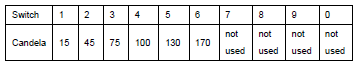
| Effective Light (cd) | 170, 130, 100, 75, 45, 15
(See Figure 3 for candela selection) |
| Operating Temperature | 0° C to 49° C (32° F to 120° F) |
| Operating Humidity | 0 to 93% RH |
| Horn Pattern | Temporal 3 |
| Strobe Pattern | 1 flash per second |
| Wire Size | 12 to 18 AWG |
| Location | Indoor wall/ceiling |
| Compatible Model | FW106 / FW106C FACP |
CAUTION
(1)To avoid electrocution that could result in personal injury or death, remove all sources of power and allow 10 minutes to discharge stored energy prior to installing or removing equipment. Install this device in accordance with all applicable codes and the Local Authorities Having Jurisdiction.
(2)Electrical supervision requires breaking the wire run at each terminal. Do not loop the signaling circuit field wires around the terminals.
(3)Check the manufacturer’s installation instructions for other equipment used in the system for any guidelines or restrictions on wiring and/or locating NACs and notification appliances. Some system communication circuits and/or audio circuits, for example, may require special precautions to assure electrical noise immunity (e.g., audio crosstalk).
(4)Check that the installed product will have sufficient clearance and wiring room prior to installing bases. Do not over tighten mounting screws as this can deform the base and may affect operation.
INSTALLATION
1.Mount the FW900/FW901 base onto a 4x4 electrical box, see Figure 2.
Figure 2. Base Installation
2.Set the strobe signal level to the desired setting. See Figure 3.
Figure 3. Candela Selector
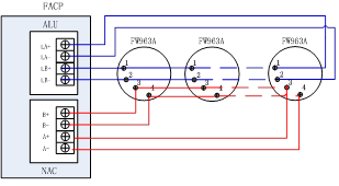
3.Connect the wires. See Figure 4.
Figure 4. Wiring Diagram (SLC / NAC)
(Note: Polarity insensitive for SLC; Polarity sensitive for NAC)
4.Wire the SLC / NAC to the device. See Figure 5.
(a)CLASS A circuit (b)CLASS B circuit
Figure 5 SLC / NAC wiring diagram
5.Combine the (horn) strobe with base – Align the (horn) strobe onto the base then and twist it in clockwise.
6.Test for proper operation. Initiate this unit from the connected FACP and observe for proper operation.
MAINTENANCE
Scheduled inspection and operational test should be carried as per requirement set out by Local Authority Having Jurisdiction.
Return the device for reparation if it fails to alarm during testing. Do not disassemble the detector without permission.


.jpg)
.jpg)
.jpg)
.jpg)