DESCRIPTIONThe FW561 is a ventilation duct detector smart designed to be used with the photo electric detector FW511. This is a UL listed device according to UL 268A and ULC-S529 for fire protection systems. Equipped with smoke detector photoelectric this unit will signal the presence of a dangerous amount of combustion product in the ventilation system. Note: these detectors are not designed to be used in open areas. The detector is equipped with an LED indicator that show if it is in alarm state. A remote testing station with LED indicator can be added for checking the operation of the detector. Refer to DOC-FW561-RI-UM for details.
ATTENTION
The products must be installed in accordance with NFPA 72, CAN/ULC-S524, and/or Canadian Electrical Code depending on country of installation. Check information of equipment used in the system by other manufacturers for any guidelines or restrictions.
The detector should never be installed in the following locations: areas with excessive exhaust fumes, kitchen areas, near fireplaces, furnace rooms, etc. Smoke detectors are not to be used with detector guards unless the combination has been evaluated and found suitable for that purpose.
NOTE
Do not paint this device.
Any material extrapolated from this document or from Maple Armor’s instructions or other documents describing the product for use in promotional or advertising claims, or for any other use, including description of the product’s application, operation, installation, and testing is the sole responsibility of the user. Maple Armor will not assume any liability for such use. In no case will Maple Armor’s liability exceed the purchase price paid for a product.
SPECIFICATION
| Nominal Voltage | 24VDC |
| Voltage Range | 17.6 to 28VDC |
| Standby Current | 0.2mA |
| Alarm Current | 30mA |
| Air Velocity Range | 300 ft/min to 4000 ft/min |
| Operating Temperature | 32°F to 100°F (0°C to 38°C) |
| Operating Humidity | 0% to 93% RH |
| Dimension | 329 x 114 x 51 mm |
| Weight (with base) | 4.6 oz (132 g) |
INSTALLATION
Figure 1 installation
To install the detector
1.Attach the drill template to the HVAC duct at desired mounting location.
2.Drill (or punch) the mounting holes where indicated.
Note: Sampling tubes longer than 36 inches must be supported at both ends of the duct.
3.If using an air sampling tube that is longer than the width of the duct, drill a 3/4-inch hole on the opposite side of the duct for tube to pass through.
4.Remove any rough edges from the holes.
5.Mount the duct smoke detector on the HVAC duct and secure it using two sheet metal screws provided.
6.If using an air sampling tube that is longer than the width of the duct, cut the tube so that approximately one inch of the tube extends through the duct. Seal the opening around the tube with an approved duct sealant.
7.Verify that all field wiring is free of opens, shorts, and ground faults.
8.Make all wiring connections as shown in Figure 2.
9.Set the module address by programmer FW412 or by panel FW106. Refer to individual manuals for details. Note: the FW561 and FW511 it connected share one address.
10.Verify the air pressure differential value falls within the specified operating range of the detector in accordance with procedures specified in “Maintenance and testing”.
11.After completing installation of the duct smoke detector, test the detector to ensure it is operating correctly in accordance with procedures specified in “Maintenance and testing”.
Figure 2 Wiring
MAINTENANCE AND TESTING
To verify the duct air velocity
In order to verify airflow direction and velocity, air must be moving through the HVAC system.
1. Drill a small hole at the point where the duct smoke detector is being installed.
2.Using the FW Air Velocity Test Kit and a suitable air velocity meter, verify that the air velocity in the HVAC duct falls within the specified operating range of the detector and note which direction the air flows.
3.If the air velocity does not fall within the specified range, relocate the detector and seal the hole in the HVAC duct.
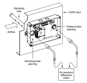
To verify the air pressure differential
In order to verify air pressure differential, air must be moving through the HVAC system.1.Connect a suitable air pressure differential meter to the sampling tube and exhaust tube openings as shown in Figure 3.
2.Verify that the air pressure differential measured falls within the specified operating range of the detector.
3.If the air pressure differential measured does not fall within the specified operating range of the detector, make sure the sampling tube air holes are not obstructed and are facing the HVAC system airflow.
Figure 3 Air Pressure measure
To clean the duct smoke detector
1.Disable the detector/zone to prevent false alarms.
2.Remove the detector’s cover then power down the detector by disconnecting the SLC wiring.
3.Using a vacuum cleaner, clean compressed air, or a soft bristle brush, remove loose dirt and debris from inside the detector housing and cover.
4. Remove dirt and other contaminants from the gasket on the detector’s cover using isopropyl alcohol and a lint-free cloth.
5.Squeeze the retainer clips on both sides of the optic housing then lift eh housing away from the printed circuit board.
6.Gently remove dirt and debris from around the optic plate and inside the optic housing.
7.Replace the optic housing and detector cover, and then connect the SLC wiring.
Return the product for reparation if it fails to flash or alarm during testing. Do not disassemble the product without permission.


.jpg)