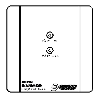
JBF5142
Two-wire, non-polar, no need for DC24V, storage function, 30V/1.5A/100ms pulse output.


| Items | Technical Parameters |
| Working voltage | DC18V-27Vmodulation type provided by the control panel |
| Wiring | Signal line: L1, L2 Polarity-free |
| Working temperature | -10~+50℃ |
| Storage temperature | -20~+55℃ |
| Relative humidity | ≤95%(40±2℃) |
| Monitoring current | ≤0.5mA(24V) |
| Alarm current | ≤10mA(24V) |
| Output capacity | DC30V/1.5A/100ms Maximum power: 2.1J |
| RF susceptibility (immunity) | 30V/M |
| Indicator | Input indicator and output indicator flash when in normal monitoring; input indicator steady on wheninput is activated; output indicator steady on when output is activated;input indicator off when input has fault; output indicator off when output has fault. |
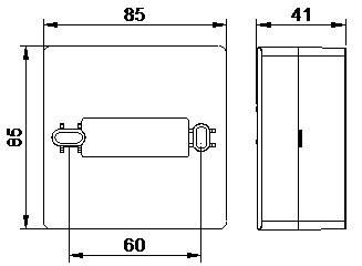
| Dimensions | 85mm×85mm×41mm |
| Addressing method | Electrical encoder |
| Address range | 1-200 |
| Communication distance | 1500m |
| Applied standard | GB 16806-2006 “Automatic Control System for Fire Protection” |