| Items | Parameters |
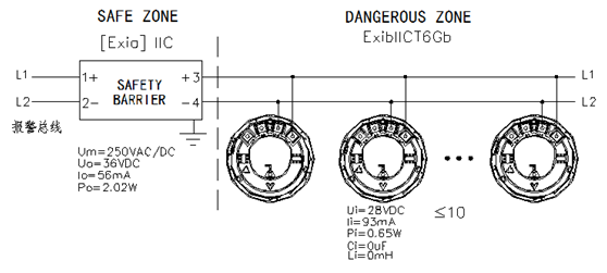
| Working voltage | DC19V-28V (typical DC24V) provided by control panel; modulation type; Through safety barrier-grid. |
| Working temperature | -10…+55℃ |
| Storage temperature | -30…+75℃ |
| Relative humidity | ≤95% |
| Monitoring current | ≤0.3mA(24V) |
| Alarm current | ≤1mA(24V) |
| Indicator | Flashin normal monitoring state; Steady-on (red) in alarm states |
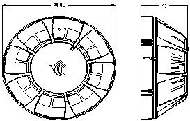
| Dimensions | Φ100mm×41mm(with base) |
| Wiring | Two-wire,polarity-free |
| Protecting area | 20-30m2 |
| Explosion proof mark | ExibIICT6Gb
Ui≤28VDC,Ii≤93mA,Pi≤0.65W,Ci=0uF,Li=0mH |
| Standard(s) complied | GB 4716-2005 “Point type heat fire alarm detector”
GB 3836.1-2010 Explosive Atmospheres Part 1: Equipment-General requirements
GB 3836.4-2010 Explosive Atmospheres Part 4: Intrinsic safety protective equipment “1” |