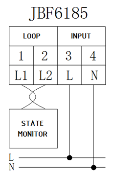
Tel:400 008 9119 Login  CN | EN

JBF6185

Two-wire, non-polar, monitoring the voltage of single phase power supply of fire equipment in real time, rotary display.
Voltage Signal Sensor

The JBF6185 AC voltage signal sensor is a bus addressing type field device for monitoring the single phaseAC voltage and transmitting the monitored signal back to the monitor in real time. When the power supply of the monitored fire equipment malfunctions, for example, power interruption, overvoltage, under-voltage and other faults, the monitor will give out sound and light alarm signal.


Product Features
(1) the sensor is encoded by electronic encoder, and the address range is 1 ~ 252.
(2) the wiring between the sensor and the monitor is of no polarity, and by which both the power supply and the data transfer of the sensors are realized.
(3) the sensor is equipped with two indicators. Flashing green light represents normal operation, and constant yellow light stands for fault.
(4) the sensor monitors the single phase AC voltageof the fire equipment power supply in real time, and can report various faults in 100 seconds, for example, power supply interruption, overvoltage, under-voltage.
(5) the sensor can transmit the monitored voltage value to the monitor to display in real time.

Technical Data

ModelJBF6185
TypeSingle loop
Monitoring objects:Voltage of single phase AC
Rated working voltage:DC 24V(loop provided)
Rated working current:5mA
Voltage monitoring rangeAC 220V
Voltage resolution:1V
Percentage of overvoltage0%~20%;
Percentage of under-voltage0%~20%;
Communication modeTwo wires, no polarity
Communication distance≤1000m
Working environmentTemperature: 0 ℃ ~ + 40 ℃;
Relative humidity: 10% ~ 93% (non-condensation)
Dimensions70mm×89.5mm×58mm(L×W×H)
Installation35mmstandard rail
 
Dimensions
•  Same as JBF61825 Installation and Wiring.

Wiring
(1) use encoder to write addresses for sensors.
(2) install the sensor on the 35mm standard guide rail in the fire power distribution box.
(3) connect the non-polarity loop bus lines to the L1/L2 terminals of the sensor.
(4) connect the output lines of the monitored single phase AC fire power supply to the L/N terminals of the sensor according to the polarity requirement.
(5) the wires of the loop should be soft double stranded wires with a diameter not less than 1.5mm2 (rvs-2 x 1.5mm2).
(6) the wires for connecting the sensor and the output ends of the power supply should be double stranded wires of a diameter no less than 1.5mm2  (RVS-2x1.5mm2).


Normal Display State of the Sensor
When the sensor circuit is connected right and the monitoring voltage is normal, the sensor LCD screen displays the current monitored voltage value and the address of the sensor in the loop, as shown in the figure below:
 
Monitored voltagesensor address (the above is no. 127)
Note: when the voltage signal sensor "voltage detecting input end” getsa power outage (or empty load), yellow fault light of the sensor is lit, and the LCD screen is dark. The monitor will displaythe info of this sensor as "power failure".