


JBE-2150
Applied to EN standard, serial connection to the loop. When a short circuit occurs in the loop, the isolation modules at both ends of the short circuit point act to isolate the short circuit.


| Category | En 54-17 Isolator module |
| Operating voltage | DC 20 to 30V(JBE protocol pulse amplitude) |
| Quiescent current | ≤0.25mA @27V |
| Short circuit current | ≤15mA @27V |
| Activation current | ≥200mA @24V |
| Maximum number of devices between isolators | 32 |
| Connection | 2-wire JBE communication bus,no polarity |
| Wiring | Twisted pair,max.wiring gauge 2.5mm²(0.5 to 2.5 mm²) |
| LED Indication | Quiescent:The two LEDs are OFF Short-Circuit in Side A: Top LED is ON Short-Circuit in Side B: Bottom LED is ON |
| Dimensions | 85 mm x85 mm x41 mm |
| Weight | 0.1 kg(including base) |
| Operating temperature | 0℃ to 40℃ |
| Storage temp | -20 to 50℃ |
| Relative humidity | ≤95%RH(no condensation nor icing) |
| Ingress protection rating | IP40 |
| Standards | EN 54-17:2005 EN 54-17:2005/AC:2007 |
| Declaration of Perf. | DoP-0370-CPR-3807-1 |
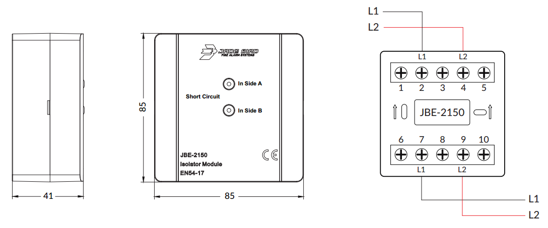
| Terminals | Connection |
| 2(3)&4(5) | Bus loop side A: L1, L2 (no polarity) |
| 7(8)&9(10) | Bus loop side B: L1, L2 (no polarity) |