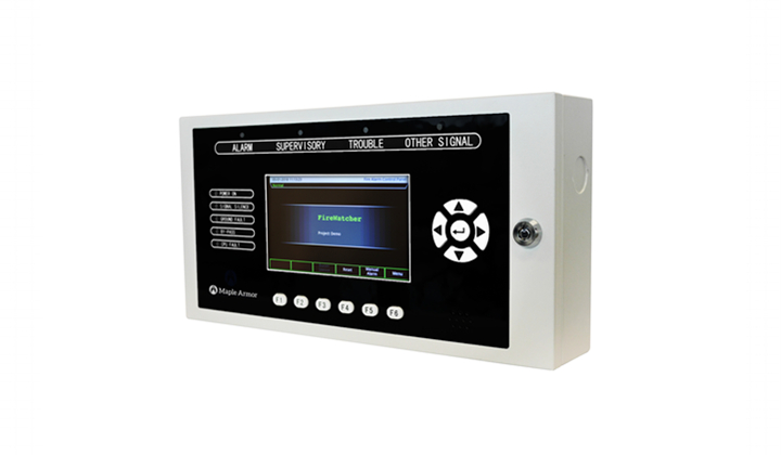
DESCRIPTIONThe FW122W, FW122R, FW122CW, FW122CR are Remote LCD Annunciators UL listed according to UL 864 and ULC-S527 for Fire Alarm Systems for indoor use.
The FW122W/FW122R/FW122CW/FW122CR have a 7” color LCD display and 800×480 resolutions, 6 auxiliary function keys and 9 LED indicators making it the most intuitive fire-alarm user interface.
In total, up to 4 annunciators can be connected to the FW106/FW106C FACP via CAN bus to form a fire emergency detection and notification network system.
ATTENTION
The products must be installed in accordance with NFPA 72, CAN/ULC-S524, and/or Canadian Electrical Code depending on country of installation. Check information of equipment used in the system by other manufacturers for any guidelines or restrictions.
NOTE
Any material extrapolated from this document or from Maple Armor’s instructions or other documents describing the product for use in promotional or advertising claims, or for any other use, including description of the product’s application, operation, installation, and testing is the sole responsibility of the user. Maple Armor will not assume any liability for such use. In no case will Maple Armor’s liability exceed the purchase price paid for a product.
SPECIFICATION
| Operating Voltage | 24VDC(Powered by Panel Aux. output) |
| Standby Current | 96mA |
| Alarm Current | 160mA |
| Operating Temperature | 32°F to 120°F (0°C to 49°C) |
| Operating Humidity | Up to 93% @ 90°F (32°C) |
| Weight | 102.3 oz (2.9kg) |
| Color | White / Red |
| Location | Indoor dry |
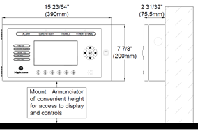
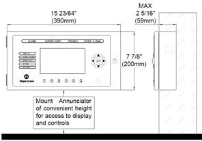
MOUNTING SPACEThe cabinet can be surface-mounted or flush-mounted. The mounting space is shown in figure 1.
(a)Surface mounting (b)Flush mounting
Figure 1. Mounting space
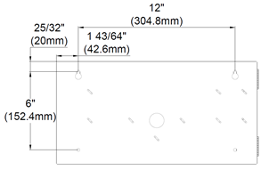
INSTALLATION SIZE
1.Select a clean, dry, shock and vibration free surface in a protected environment.
2.Position the cabinet clear of obstructions so that the door opens freely and the controls and indicators are easily accessible.
3.Mark the locations of the two upper mounting bolts of the cabinet on the wall.
4.Drill the two holes located in the previous step and screw in the top bolts, leaving a small gap between the wall and each top bolt.
5.Place the cabinet over the two top bolts and allow it to slide down over the bolts.
6.Mark, drill, and install the two bottom bolts in the cabinet.
7.Tighten all four bolts securely against the back wall of the cabinet.
Figure 2. Installation Size
WIRING
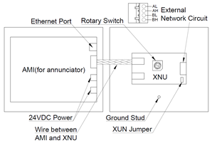
Figure 3. Connection
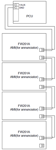
1.The 24VDC power comes from the auxiliary output(power limited) of FW106 FACP. Two connectors are available(one for input and the other for output) as shown in figure 3 and figure 4.
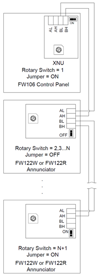
2.External network circuit (class B, power limited) can address up to 4 remote annunciators. When connecting annunciators on the external network circuit, the data wires must be daisy chained and with no T-taps to preserve the integrity of the data. The rotary switch and jumper should be set correctly as shown in figure 5.
3.Connect the ground wire using the terminal provided.
4.An Ethernet standard plug is provided for temporary connection to a computer for panel programming.
Figure 4. 24VDC Connection Figure 5. External Network Circuit
(N is the quantity of annunciator)