JBE-2125
Applied to EN standard, connect to the loop, the output end receives activating command from the control panel and start the connecting devices.


| Category | EN54-18 |
| Working voltage | DC 16-30 V (JBE protocol pulse amplitude) |
| Connection | 2-wire JBE communication bus, no polarity |
| Wiring | Twisted pair, max. wiring gauge 2.5 mm2 |
| Quiescent current | ≤0.25mA @24V |
| Activation current | ≤1mA @24V |
| Output | Maximum 1A@24V |
| Clean contact rating | 2A/30V DC |
| Input EOL Resistor | 10 kΩ |
| Output EOL Resistor | 10 kΩ |
| Working temperature | 0 to +40ºC |
| Storage temperature | -20 to +50℃ |
| Environment Humidity | ≤ 95% RH (no condensation nor icing) |
| Addressing method | Soft addressing with tool JBE-AT1, non-volatile |
| Address range | 1-200 |
| LED Indication (Active output mode) | Healthy: "Input" and "Output" LED flashes Output Activation: "Output" LED is constantly on Feedback: "Input" is constantly on. Input Fault:"Input" is off and "Output" flashes. Output or 24V Fault: "Input" and "Output" are off |
| LED Indication (Relay Output mode) | Healthy: "Input" LED flashes, "Output" LED off Fault: "Input" and "Output" LED off |
| Dimensions | 85 mm ×85 mm x41 mm |
| Weight | 0.1 kg(including base) |
| IP rating | IP40 |
| Standars | EN 54-18:2005 EN 54-18:2005/AC:2007 |
| Declaration of Perf. | Dop-0370-CPR-3806-1 |
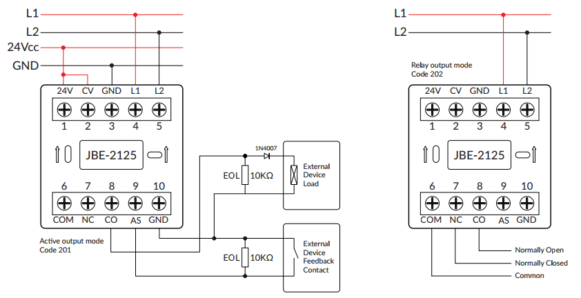
| Terminals | Connection type |
| 1&3 | Power supply 24Vcc, GND |
| 2 | 24V IN Connect to contact 1 if needed. |
| 4&5 | Signal loop L1, L2 (no polarity) |
| 8&10 | CO, GND, used when need to 24V output, connect to equipment in the field. EOL resistor is needed |
| 9&10 | AS+, GND, connect feedback contacts. EOL resistor is needed |
| 6&7&8 | COM (Common), NC (Normally Closed), CO (Normally Open) are the relay connections when used in Relay output mode. |