JBF6186
Two-wire, non-polar, monitoring the voltage of three-phase three-wire power supply of fire equipment in real time, rotary display.


The JBF6186 voltage signal sensor is a bus addressing type field device for monitoring 3-phase 3-line dual power supply system. When the power supply of the monitored fire equipment malfunctions, for example, power interruption, overvoltage, under-voltage and other faults, the sensor will transmit the above fault signals to the monitor and the monitor willgive out sound and light alarm signal.
| Model | JBF6186 |
| Type | Duelloop |
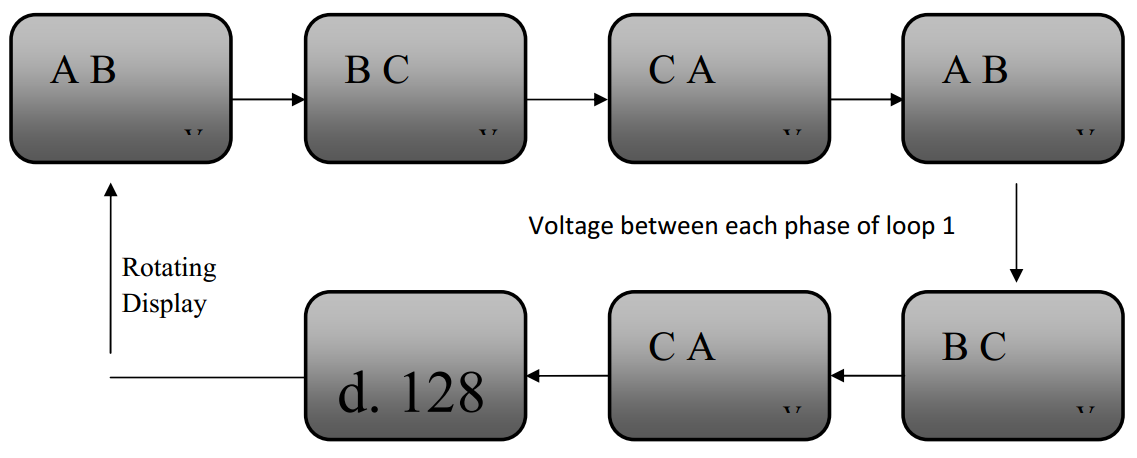
| Monitoring objects: | Voltage of 3-phase 3-line power supply |
| Rated working voltage: | DC 24V(loop provided) |
| Rated working current: | 5mA |
| Voltage monitoring range | AC 380V |
| Voltage resolution: | 1V |
| Percentage of overvoltage | 0%~20%; |
| Percentage of under-voltage | 0%~20%; |
| Communication mode | Two wires, no polarity |
| Communication distance | ≤1000m |
| Working environment | Temperature: 0 ℃ ~ + 40 ℃; Relative humidity: 10% ~ 93% (non-condensation) |
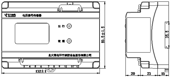
| Dimensions | 132mm×89.5mm×58mm(L×W×H) |
| Installation | 35mmstandard rail |