| Executive Standard | GB 28184-2011 “Power Supply System for Fire Protection Equipment” |
| Communication Methods | No polar, two wires |
| Capacity | Single loop of 252 points |
| Communication Distance | ≤1000m |
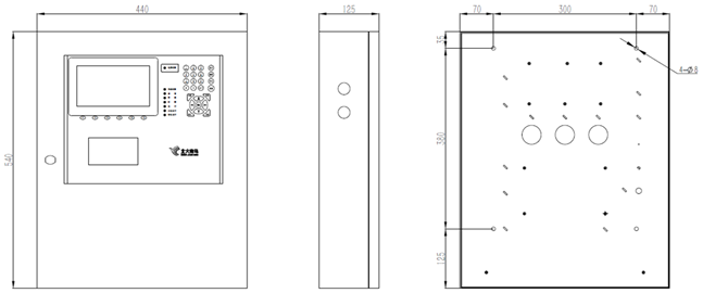
| Installation | Wall-mounted |
| Main Power Input | AC220V,50±1Hz |
| Power Capacity | System Power: 24V/2A, External Power: 24V/3A |
| Standby Power | 12V/7Ah×2 |
| Operation Level | 3 levels of access management, for management of different type of users. |
| Display Function | English, true color |
| Print Function | Configuration of micro thermal printer, can select and print system operating status in real time |
| Storage Capacity | ≥100000 pieces |
| Operating Temperature | 0℃~+40℃ |
| Storage Temperature | -20℃~+50℃ |
| Relative Humidity | ≤93% No condensation |
| Alarm Sound Pressure Level | 65dB~85dB; |
| Dimension | 440mm×125mm×540mm(W×L×H) |