| Item | Parameters |
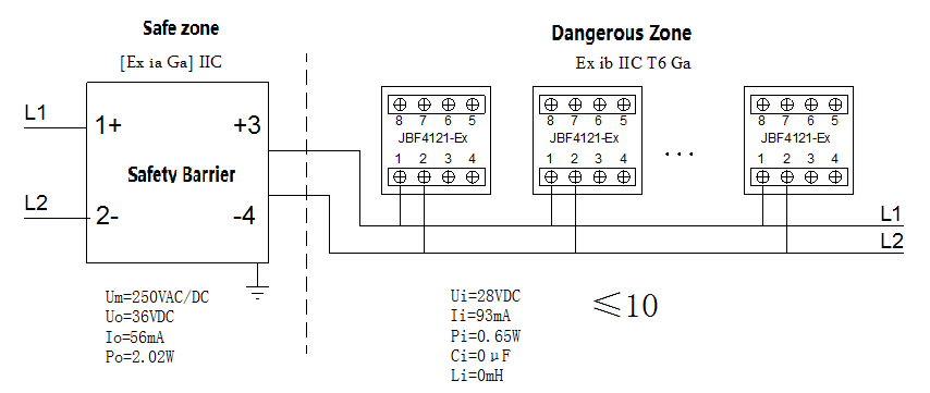
| Working voltage | DC 19-28V provided by control panel, modulation type (must through safety barrier) |
| Monitoring current | ≤0.3mA (24V) |
| Alarm current | ≤1mA (24V) |
| Explosion proof mark | Ex ib IIC T6 Gb |
| Contacts capacity | DC30V/0.1A |
| Addressing method | Electronic addressing |
| Address range | 1-200 |
| Operating temperature | -10—+55℃ |
| Storage temperature | -30—+75℃ |
| Relative Humidity | ≤95%RH (40±2℃) |
| Indicators | Flashes in monitoring state, constant on (red light) when in alarm state. |
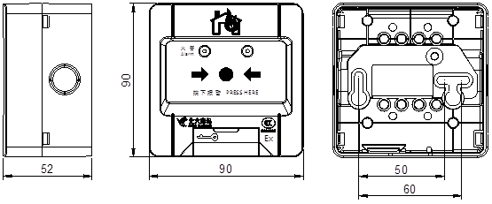
| Dimensions | 90mm × 90mm × 52mm (L × W × H) |
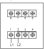
| Wires | Two-wire bus, non-polarity |
| Weight | 160g |