The manual call point consists of the start-up switch and the corresponding processing circuit. When there is a fire alarm, manually press the button, the button switch is closed, and the alarm signal is sent to the control panel via the loop, and the fire alarm indicator of the manual call point will be changed from flashing (inspection state) to constant light to show the alarm status. If the user controls the sound and light alarm device in the field through the passive normally open contacts of this manual call point, the passive normally open contacts will be closed when the button is pressed, and the alarm device will be activated. The phone indicator on the manual call point flashes if the point gets connected to the fire telephone system.
Product Features
● Built-in microprocessor, performance is stable.
● Adopt SMT process, high reliability, good consistency.
● Two-bus system without polarity requirements, and the communication distance is up to the 1000m at a very low power consumption.
● Electronic addressing with specialized device.
● Simple operation. Press the operating panel by hand to report fire alarm to the control panel.
● After operating panel is pressed, the manual call point can only be reset using the key accompanied.
● The manual call point features a new buckle structure and a thin design.
● The phone jack is located on the bottom of the manual call point. For easy identification, is added to the front to mark the position.
Technical Data
| Item | Parameters |
| Working voltage | DC 19-28V provided by control panel, modulation type |
| Monitoring current | ≤0.3mA (24V) |
| Alarm current | ≤1mA (24V) |
| Contacts capacity | DC30V/0.1A |
| Addressing method | Electronic addressing |
| Address range | 1-200 |
| Indicators | Flashes in monitoring state, constant on (red light) when in alarm state. |
| Phone indicator | Flashes when the device gets access to the fire telephone system. |
| Operating temperature | 10—+55℃ |
| Storage temperature | -30—+75℃ |
| Relative Humidity | ≤95%RH (40±2℃) |
| Wires | Two-wire bus, non-polarity |
| Weight | 103g |
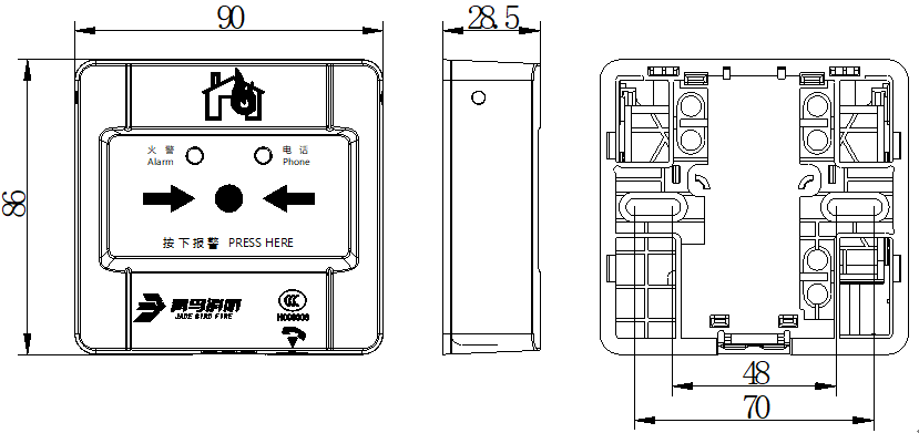
| Dimensions | 90mm × 86mm × 28.5mm (L × W × H) |
1) After wiring construction, the base is secured to the wall by pre-buried box or using expansion bolts. The mounting hole distance is 60mm (compatible with 50mm mounting hole distance).
2) The manual call point adopts RVS2×1.5mm2 twisted pair connecting to the control panel.
3) Write address (1-200) to the manual call point using electronic encoder.
4) Put on the front cover after checking the wiring.
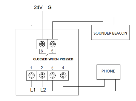
● Terminals 1 and 2 connect bus L1 and L2, and polarity is reversible.
● Terminals 3 and 4 connect phone line, no polarity required.
● Terminals 5 and 6 are normally open contacts. They close when the manual call point button is pressed, and activate the sound and light alarm device. It’s strictly prohibited to use this contact to control high-power equipment or strong electrical equipment.
● Put on the front cover after checking the wiring.
Conduct alarm test regularly, recommended every six months.