


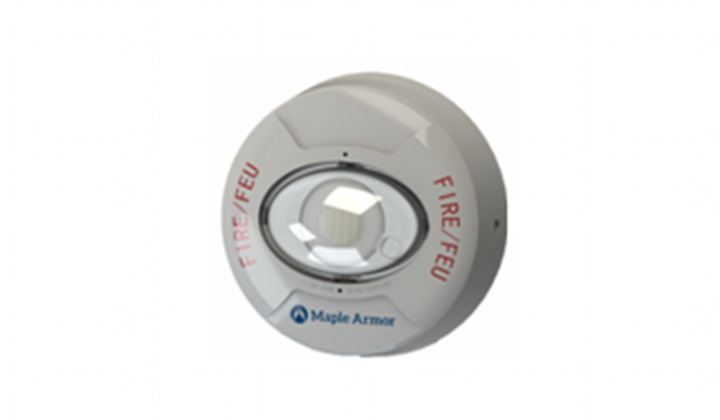
FW982R
UL listed, connect to NAC, polar two-wire, visual alarm


| Operating Voltage | 16 to 33 VDC/FWR | ||||||
| RMS Operating Current @16 Vdc(mA) | 130cd | 105cd | 85 cd | 50 cd | 35 cd | 20 cd | |
| FW962R FW962W | 164 | 126 | 85 | 55 | 47 | 30 | |
| FW982R FW982W | 156 | 119 | 80 | 49 | 43 | 28 | |
| RMS Operating Current @16Vfwr (mA) | 130cd | 105cd | 85 cd | 50 cd | 35 cd | 20 cd | |
| FW962R FW962W | 187 | 158 | 102 | 66 | 58 | 38 | |
| FW982R FW982W | 154 | 150 | 97 | 61 | 53 | 35 | |
| Sound Level (dBA) | Voltage | 16V dc/fwr | 24V dc/fwr | 33V dc/fwr | |||
| UL Reverberant | 77 | 81 | 85 | ||||
| ULC Anechoic | 85 | 88 | 91 | ||||
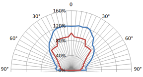
| Directional Characteristics | Horizontal Axis | Angle | OSPL (dBA) | ||||
| 0° (ref) | 0 (ref) | ||||||
| ± 44° | -3 | ||||||
| ± 54° | -6 | ||||||
| ± 90° | -10.5 | ||||||
| Vertical Axis | Angle | OSPL (dBA) | |||||
| 0° (ref) | 0 (ref) | ||||||
| ± 52° | -3 | ||||||
| ± 55° | -6 | ||||||
| ± 90° | -12 | ||||||
| Effective Light (cd) | 130, 105, 85, 50, 35, 20 (See Figure 3 for candela selection) | ||||||
| Operating Temperature | 0° C to 49° C (32° F to 120° F) | ||||||
| Operating Humidity | 0 to 93% RH | ||||||
| Horn Pattern | Temporal 3 | ||||||
| Strobe Pattern | 1 flash per second | ||||||
| Wire Size | 12 to 18 AWG | ||||||
| Location | Indoor wall/ceiling | ||||||
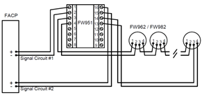
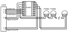
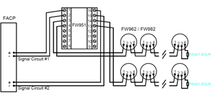
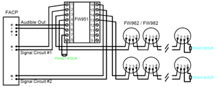
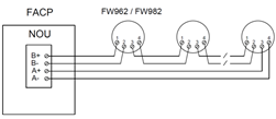
| Compatible Model | FW951 Sync Module, FW106 / FW106C FACP | ||||||
.jpg)
.jpg)

.jpg)