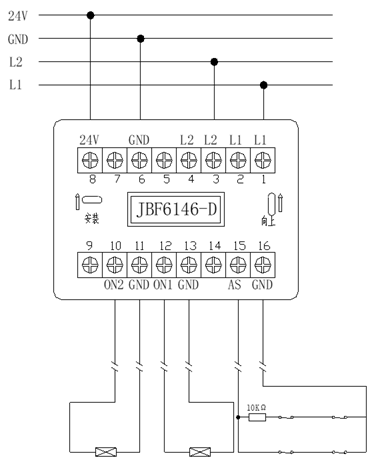
Tel:400 008 9119 Login  CN | EN

JBF6146-D

Four-wire, applicable to normally open double door that are normally with power. When activated, the power is cutoff and it close the electric door closer and electromagnetic discharger.
Input/Output Module
The function of the product is similar to that of JBF6142-D, except that this product is designed especially for the normally open double fire door. It has two sets of output that controlling two door closers of the normally open doors and occupies only one address on the loop.

Product Features
•  Embedded micro-processer.
•  Supplied by 24V power supply; gives out 24V relay output.
•  Two-wire polarity-free loop, low power consumption.
•  A communication distance of 1500m.
•  Twisted pair cable is recommended in the installation. The cross-section of the cable should not be less than 1.5mm².
•  Electrical isolation between signal processing circuit and input/output checking circuit; reliable performance.
•  Plug in structure, easy to install and maintain.
•  With state monitoring and fault detection functions.

Technical Data
ItemsTechnical Parameters
Power inputDC 16-30V
LoopTwo-wire, polarity-free, modulation type;
Workingcurrent≤0.1mA
Relay outputDC24V/300mA
Addressing methodElectrical encoder
Address range1-252
IndicatorMonitoring: “operation” red indicator flashes and “output” red indicator steady on.
Activation and feedback: “operation” red indicator brightly flashes, and “output” red indicator is off;
Fault: “operation” red indicator flashes twice in a row.
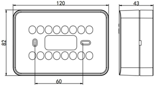
Dimensions120mm ×82mm ×43mm(L×W×H)
 
Structure and Dimensions
 
Wiring
•  L1 (terminal 1, 2) and L2 (terminal 3, 4): polarity-free, connect to the loop.
•  24V (terminal 8) and GND (terminal 6): connect to 24V DC power. Pay attention to the polarity.
•  Input function: AS (terminal 15) and GND (terminal 16): connect to the feedback terminals (volt-free).
•  Output function: ON2(terminal 10),ON1(terminal 12),GND(terminal 11, terminal 13) connect to the equipment to be controlled and continuously outputs 24V. After activation, ON1 and GND, ON2 and GND stop outputting 24V. 
Notes:

•  The feedback terminals of the connecting equipment that connect to AS and GND should add a 10KΩ EOLR in series.
•  Default factory settings: after activation, ON1 is first activated, and ON2 is activated after 6 seconds. The duration of 6 seconds can be changed using encoder, range: 1-30 seconds.