


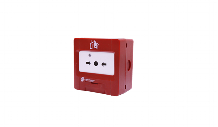
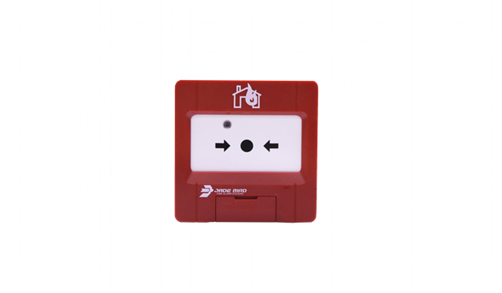
JBE-2100
Applied to EN standard, JBE-AT1 coding. When front panel of the MCP is pressed down, MCP sends alarm signal to the control panel.


| Category | EN 54-11 type A indoor MCP |
| Working voltage | DC19-28V(JBE protocol pulse amplitude) |
| Connection | 2-wire JBE communication bus, no polarity |
| Wire size | 0.5 – 2.5 mm2 |
| Quiescent current | ≤0.3mA @24V |
| Alarm current | ≤1.0mA @24V |
| Clean contact rating | 0.1A/30VDC |
| Working temp. | -10℃~55℃ |
| Storage temp. | -30℃~75℃ |
| Environment Humidity | ≤95%RH (no condensation nor icing) |
| Addressing method | Addressing tool JBE-AT1 |
| Address range | 1-200 |
| Red LED Indication | Flashingwhen polled. Steady on when in alarm. |
| Dimensions (LxWxH) | 90×90×52mm |
| IP rating | IP40 |
| Weight | 0.16kg(including base) |
| Standards | EN 54-11 |
| Declaration of Perf | DoP-0370-CPR-3803-1 |
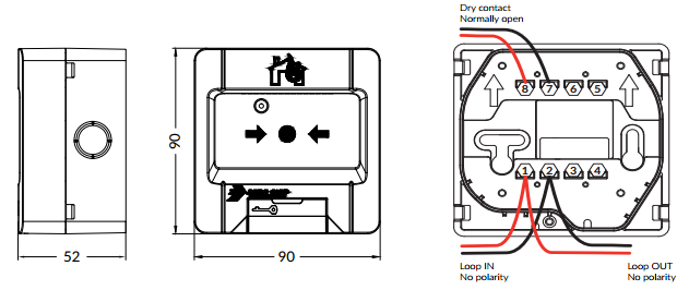
| Terminals | Connection |
| 1 & 2 | Signal loop L1, L2 (no polarity) |
| 7 & 8 | (Optional) Normally open dry contact switch max rating: 0.1 A -30 Vcc |
| 3,4,5,6 | Not connected |