| TERMINALS | TERMINALS AND WIRING INSTRUCTIONS |
| 24V,G | 24V output, providing electricity for devices in the field |
| FAULT | Output passive close signal when reports fault. |
| FIRE | Output passive close signal when reports fire. |
| SL-,SL+ | 6 loops to directly control large fire protection equipment. Polar lines. |
| L+,L- | 4 non-polar loops. L1 and L2 have 80 addresses each. L3 and L4 have 200 addresses each. Loops connect with detectors, sounder beacons, modules,etc |
| IN1-,IN1+ | Input terminal 1, connecting signal input lines and 10K 1/4W resistance |
| IN2-,IN2+ | Input terminal 2, connecting signal input lines and 10K 1/4W resistance |
| FB-,FB+ | Suppression status signal, connecting10K 1/4W resistance |
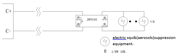
| C-,C+ | Suppression activation,connecting suppression equipment(solenoid valve type)with resisitance, see diagram 1. Connecting electric squib(aerosols)suppression equipment with JBF5183 electric squib junction box, see diagram 2. |