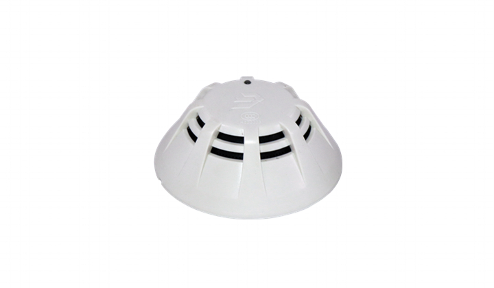
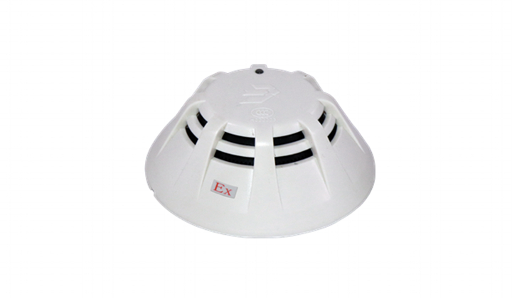
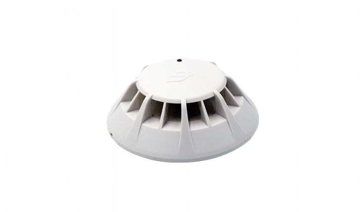
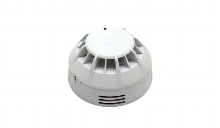
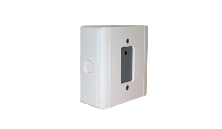
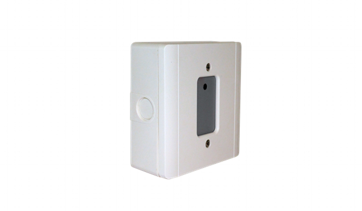
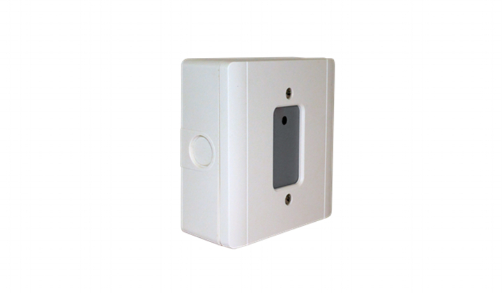
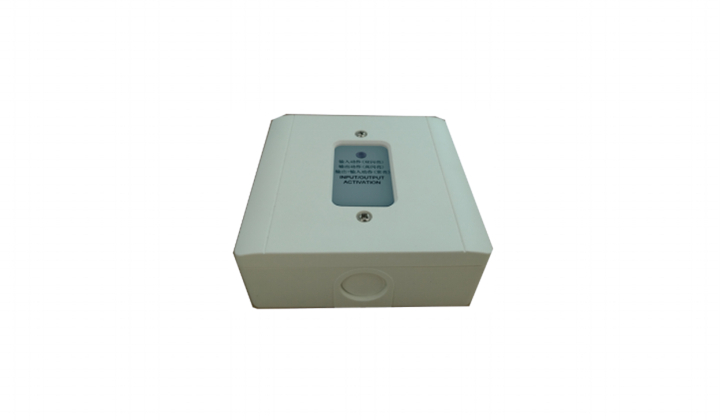
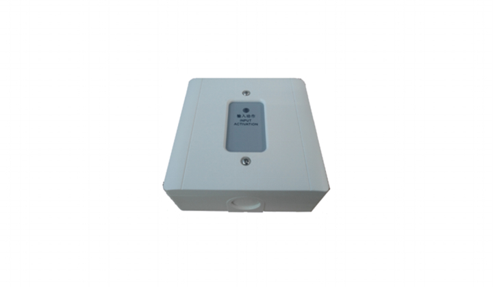
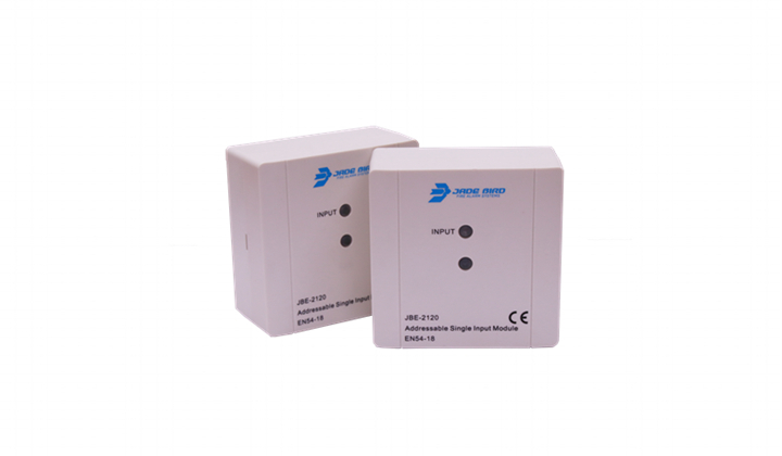
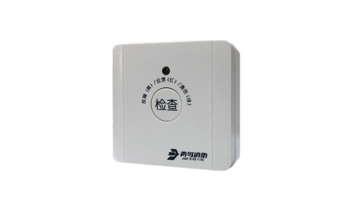
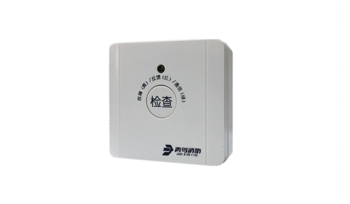
DESCRIPTIONThe FW841 conventional zone module is intended to allow Maple Armor intelligent fire alarm control panels to interface and monitor 2-wire conventional detectors in retrofit applications.
The initiating zone can support a mix of 2-wire conventional automatic detectors as well as normally open dry contact alarm initiating devices such as mechanical heat detectors and manual stations.
The Initiating Zone power can be derived either from the SLC loop or be provided by an external UL/ULC listed 24VDC power supply.
ATTENTION
The products must be installed in accordance with the NFPA 72, the CAN/ULC‐S524, the CAN/ULCS536, and the Canadian Electrical Code depending on the country of installation. Check information of equipment used in the system by other manufacturers for any guidelines or restrictions.
NOTE
Do not paint this device.
Any material extrapolated from this document or from Maple Armor’s instructions or other documents describing the product for use in promotional or advertising claims, or for any other use, including description of the product’s application, operation, installation, and testing is the sole responsibility of the user. Maple Armor will not assume any liability for such use. In no case will Maple Armor’s liability exceed the purchase price paid for a product.
SPECIFICATION
| SLC Nominal Voltage | 24VDC |
| SLC Voltage Range | 15 to 28VDC |
| SLC Standby Current | 10mA |
| SLC Active Current | 31mA |
| External Nominal Input Power Voltage | 24VDC |
| External Input Power Voltage Range | 16 to 28VDC |
| Max. Line Impedance (Output) | 50 Ω |
| Max. Impedance for Grounding | 6.6 KΩ |
| Compatible EOLR | 2k to 50K Ω |
| Operating Temperature | 32°F to 120°F (0°C to 49°C) |
| Operating Humidity | 0% to 93% RH |
| Mounting | FW800 base |
| Dimension | 120 mm (L) x 120 mm (W) x 45 mm (H) |
| Weight (with backbox) | 8.7 oz (247 g) |
| Wiring Gauge | 12 to 18 AWG |
INSTALLATION
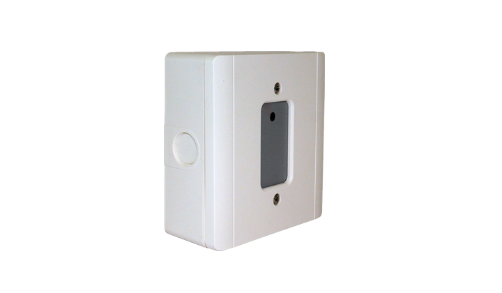
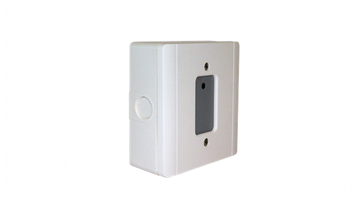
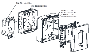
1.Mount the FW800 base onto a 2X4 or 4x4 electrical box using the screws provided, as illustrated in Figure 1.
Figure 1 Installation Diagram
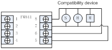
2.Connect the wires, see Figure 2. There is polarity sensitive between terminal 1 and terminal 2. All circuits are power-limited.
Figure 2 Wiring Diagram (SLC/DCL)
3.Wire the SLC/DCL to the module, as illustrated in Figure 3.
(a) Class A or DCLA Circuit (b) Class B or DCLB Circuit
Figure 3 SLC/DCL Wiring Diagram
4.Connect the input line circuit wires. See Figure 4. The maximum line impedance for input circuit is 50Ω.
(a) Class A Circuit (b) Class B Circuit
Figure 4 Wiring Diagram (Input Line Circuit)
5.Combine the assembled unit to the base using the screws provided.
6.Apply power to the control unit.
PROGRAMMING
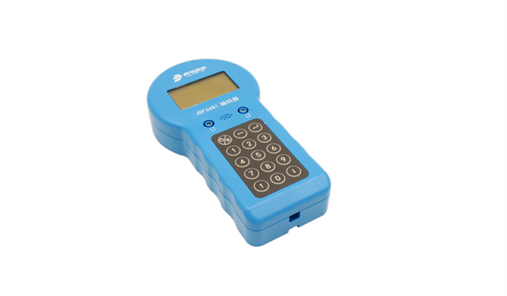
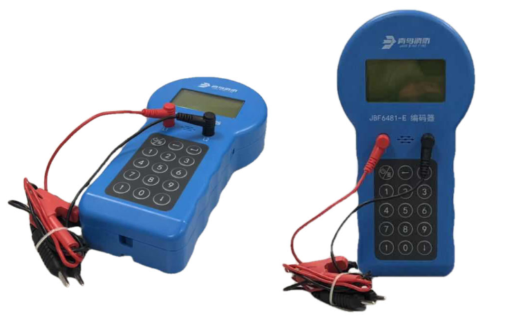
The module must be programmed to a valid address before use. A valid must be in 1~252 and cannot be duplicate with other device in same loop. Refer to the manual of programmer FW411/FW412 and Panel FW106 to set the device address. Disconnect wire at terminal 1 and 2 before programming.
TESTING
1.Before testing, inform the proper authorities that the system is undergoing maintenance and will temporarily be put out of service. Disable the system to prevent unwanted alarms.
2.Make sure the indicator LED on the detector’s surface is flashing (once every 3 seconds when powered by external 24VDC, or twice every 3 seconds when powered by SLC loop). Flashing 3 times every 3 seconds indicates the module is in trouble condition (for example missing EOLR). Failure to flash indicates a non-functioning module or a faulty wiring. Check the wiring and remount the module.
3. Trigger the input switch to activate a fire signal. The LED should turn to red steady on. Check the event occurrence displayed on LCD of the controller and verify.
4.Once the testing is completed, set the system back to normal operation and inform proper authorities.
MAINTENANCE
Return the module for repair if it fails to flash or alarm during testing. Do not disassemble the module without permission.
































.jpg)
.jpg)
.jpg)
.jpg)