1Overview

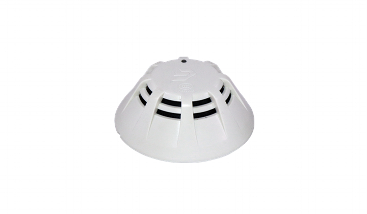
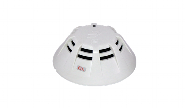
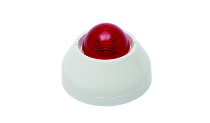
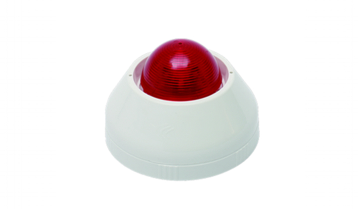
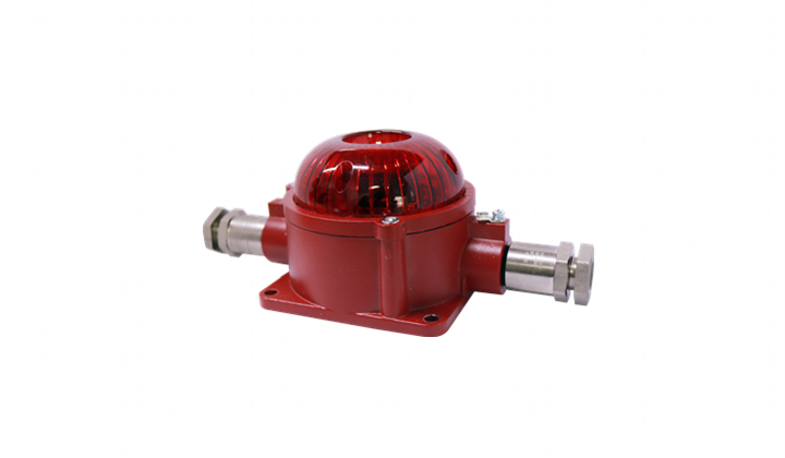
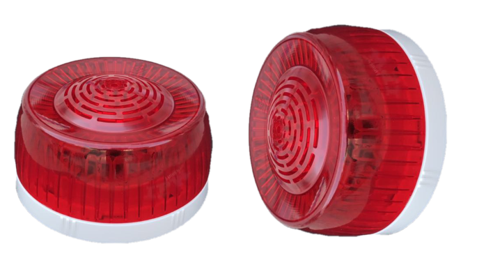
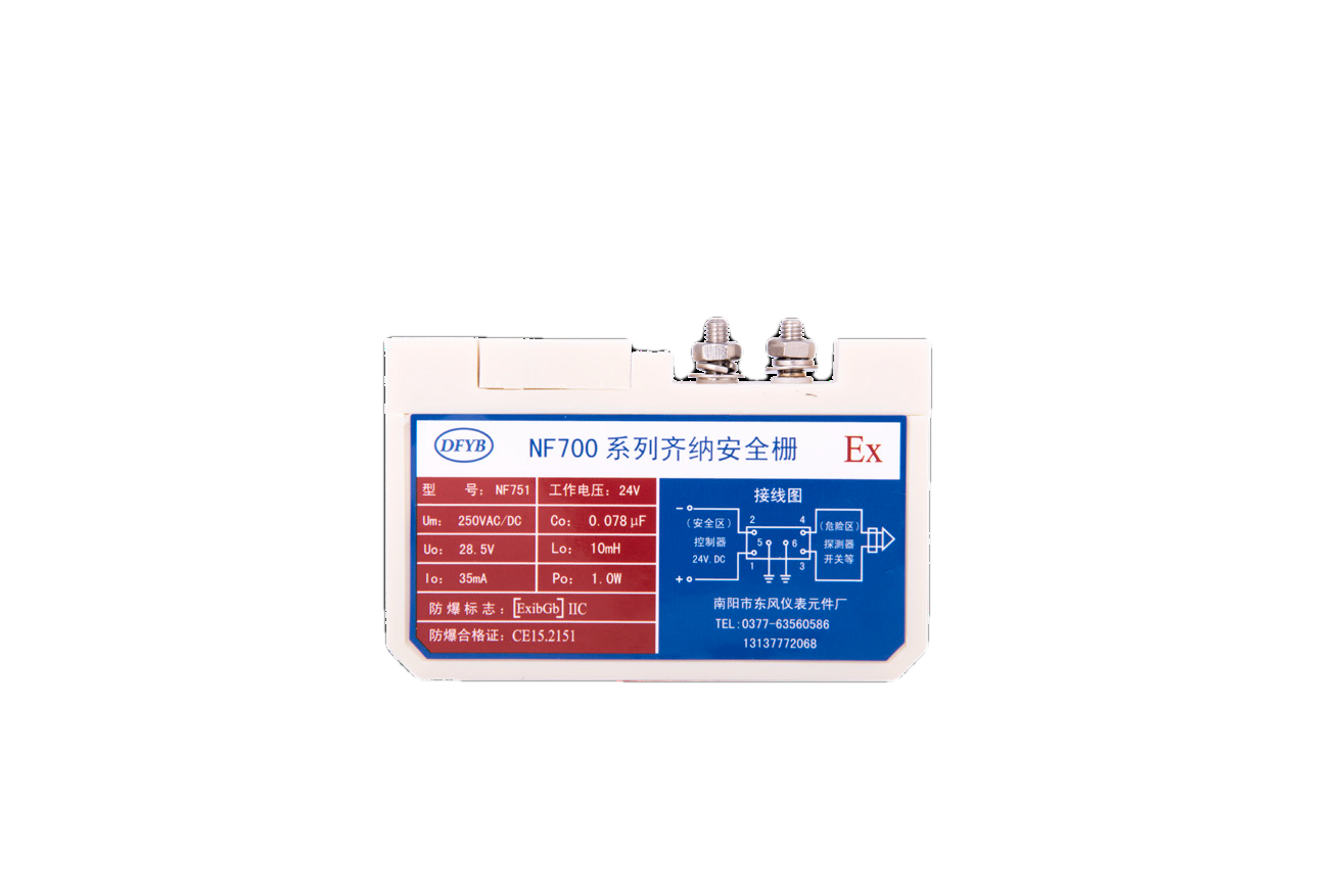
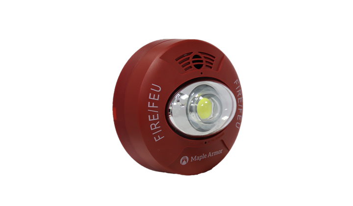
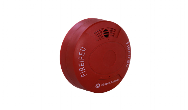
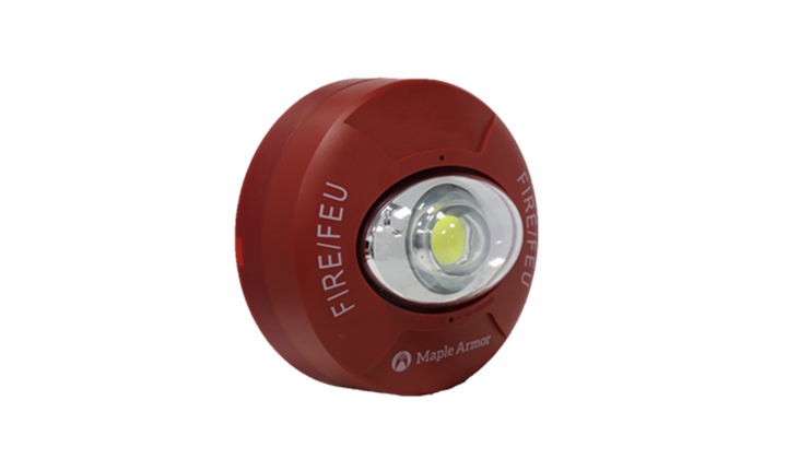
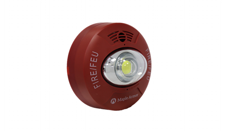
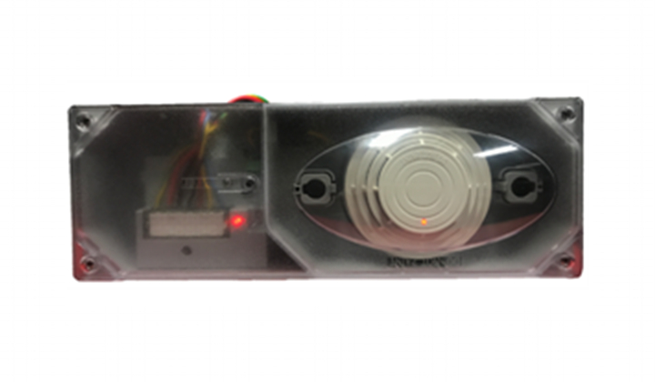
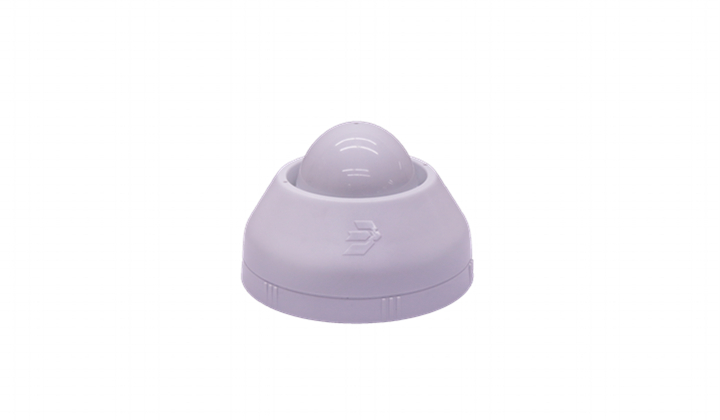
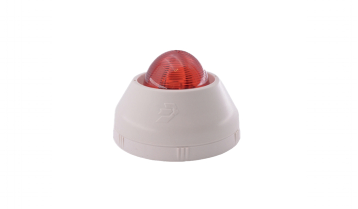
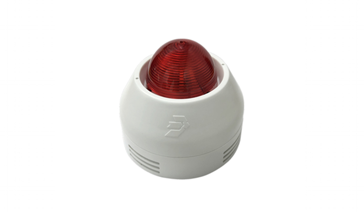
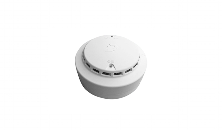
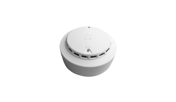
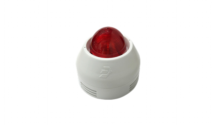
JBF5174-Ex fire sounder beacon is used in JBF-11SF and JBF50XX fire alarm systems. When a fire occurs in a public place, the control panel sends out an alarm command, and the fire sounder beacon gives out a high-decibel alarm, and the LED flashes. The product is intrinsically safe, and with the explosion-proof barrier, it can be installed indoors in non-residential hazardous areas I and II, for example, the petrochemical zone. The safety barrier must have [Exib Gb] IIC or above certificates.
1.1 Product features
- Built-in fire industry specialized Crested Ibis microprocessor;
- SMT technology;
- Two-wire bus technology, polarity-free;
- Twisted-pair wire shall be used in construction, and its cross section shall not be less than 1.0mm2;
- Two different alarms, separate sound, separate light, or other states can be set by encoding.
1.2 Applied scope
- Fire sounder beacon connects to JBF-11SF and JBF50XX series fire alarm control panel.
- Suitable for indoor (non-residential) public places, such as hotel rooms, office buildings, libraries, theaters, postal buildings, etc.
- Suitable for petrochemical zones and other areas that belong to indoor non-residential hazardous areas I and II.
- The application design conforms to the national standard GB 50116-2013 Code for Design of Automatic Fire Alarm System.
- Applies to nation standard GB 50116-2013 “Code for design of automatic fire alarm system”
1.3 Naming of model

2Operation Theory
The fire sounder beacon consists of two-wire bus contacts, alarm circuit, LED circuit and processing circuit. When fire occurs, the control panel sends fire alarm command, and the sounder beacon gives out sound alarm and its LED flashes.
3Technical Data
Environment features
| Working temperature | -10~+55℃ |
| Storage temperature | -20~+65℃ |
| Relative humidity | ≤95% (no condensation) |
Explosion proof
| Explosion-proof mark | Ex ib IIC T6 Gb |
| Explosion-proof certificate number | CE20.2769X |
Electrical features
| Working voltage | DC18V-28V, modulation type, provided by control panel (must connect safety barrier) |
| Monitoring current | ≤ 205μA |
| Alarm current | ≤ 6mA (DC24V) |
| Intrinsic safety parameters | Ui=28V Ii=93mA Ci=50pF Li=0mH Pi=1.0W |
| SPL | 75.0dB~115.0dB (DC24V, A weight) |
| Tone cycle | 4.0s~5.0s |
| Flashing frequency | 1.0Hz~1.5Hz |
Communication features
| Wiring | Two wire (polarity-free) |
| Address range | 1~200 |
| Addressing method | Electronic encoding |
| Maximum communication distance | 1000m |
Compatibility
| Connect to JBF-11SF series control panel, JBF50XX series control panel |
Mechanical features
| Appearance | PANTONE T085-2-1 transparent red |
| Housing material | PC (front cover) +ABS (base) |
| Weight | About 185g |
| Dimensions | Φ100mm×H52mm (base included) |
| IP grade | IP34 |
Certification
| Fire certificate, Explosion-proof certificate |
Applied standards
| 1) | GB 26851-2011 “Audible and/or visual fire alarm signaling appliances” |
| 2) | GB 3836.1-2010 “Explosive atmospheres - Part 1: Equipment-General requirements” |
| 3) | GB 3836.4-2010 “Electrical apparatus for explosive gas atmospheres Part 4: General requirements” |
4Installation
4.1 Installation steps
- Fire sounder beacon adopts unfolded installation.
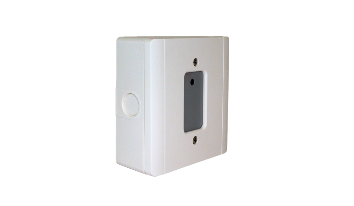
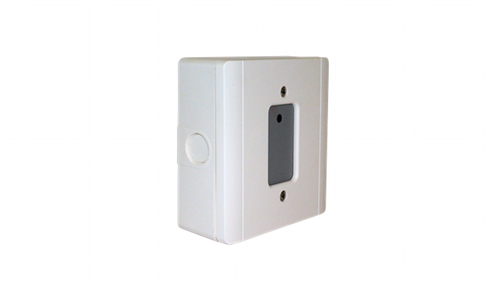
- After cable laying, fix the base of fire sounder beacon onto wall using M4 screws, pitch of holes 45mm~68mm, as shown in Figure 1.
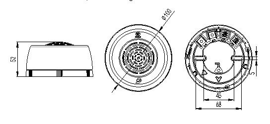
Figure 1 Appearance and Dimensions
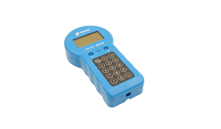
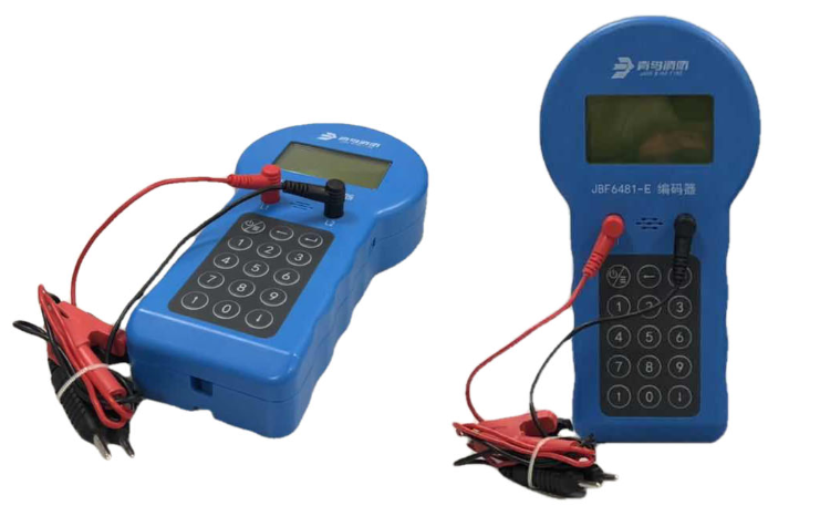
- Before installation, write address to the product by the electronic encoder in the safe area. The address written is in accordance with the address in the project software.
- The two-wire fire bus is connected to Terminals 1, 2 after passing through the safety barrier. The wiring is polarity free.
- Install the fire sounder beacon after the wiring check, to prevent possible damage caused by improper installation.
- Up to 2 fire sounder beacons can be connected to 1 safety barrier as shown in Figure 2.
Figure 2 Wiring
Notes: the parameters of the barrier should follow:
Ui≥Uo, Ii≥Io, Pi≥Po, Ci+Cc≤Co, Li+Lc≤Lo;
Cc, Lc: The cable (or wire) connecting the safety gate to the alarm allows the total distribution of capacitance and inductance. See GB 3836.4-2010 standard for the detailed meaning of other symbols.
4.2 Commissioning
- Write address to fire sounder beacon by electronic encoder, address range: 1~200.
- After successfully writing the address, connect the fire sounder beacon through safety barrier to the control panel to register the device.
- In case of fire, the control panel sends out fire alarm command and the fire sounder beacon flashes and sounds alarm.
- Set different fire sounder beacon working modes by writing special addresses to the product.
| Working mode | Special addresses | Notes |
| Sounder Beacon | 201 | |
| Sounder | 202 | |
| Beacon | 203 | |
- Set alarm sound type of the fire sounder beacon:
| Alarm sound | Special addresses | Notes |
| Horn | 204 | |
| Beep | 205 | |
- Set different fire sounder beacon status by writing special addresses to the product.
| Status | Special addresses | Notes |
| Addressable | 206 | |
| Reset to factory default | 208 | Sounder beacon, addressable |
5Troubleshooting
| Problems | Causes | Solutions | Notes |
| The control panel reports fault | Loop is not correctly connected | Check the wiring. | |
| The address of the sounder beacon is not the same as the one in the engineering software. | Write address to the product following the project engineering software. | |
| Unable to register the device | The device is not addressed. | Address the device using encoder. | |
| Loop is not correctly connected | Check the wiring. | |
| Address number is out of range | Address range: 1-200 | |
6Maintenance and Repair
- Daily maintenance, maintenance, and calibration
- Conduct alarm test regularly, every six months recommended.
7Out-of-box Checking
The package should have the following items:
| Fire sounder beacon | 75 pics/Package (no base) |
| Manual | 8 pieces/Package |
After opening the package, please check the appearance and functions of the product. Should there be any loss or damage to the sounder beacon, please contact us soon. Once determined that the damage is not caused by human factors, we will replace it for the customer immediately.
8Disclaimer
- Use of the product must be in strict accordance with the description of this manual for installation and commissioning.
- The wiring of the inlet side of the safety barrier and that of the outlet side must be separated (keeping a minimum 50mm distance).
- The product is explosion-proof certificated. It’s forbidden to replace or change components or structure of the product.
- The Company reserves the final interpretation of this manual.
Warning: The housing material of the product is plastic. There is risk of electrostatic charge. Please wipe with a wrung-out wet cloth when cleaning to avoid friction.
To avoid ignition risk caused by electrostatic charge, it’s strongly advised not to touch or clean the product in the dangerous zone. Make sure such conducts to be carried out in a place with good ventilation and no gas leakage, and wipe the outside with a wrung-out wet cloth. Do not use dry cloth to wipe.
