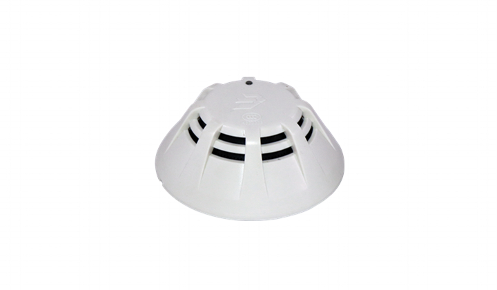
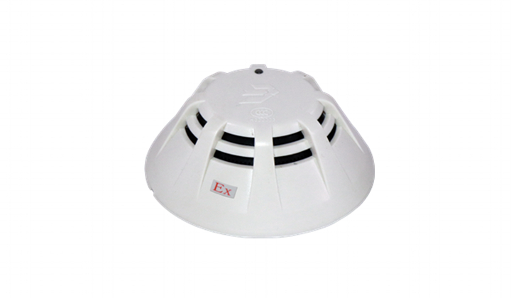
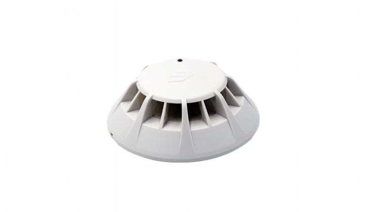
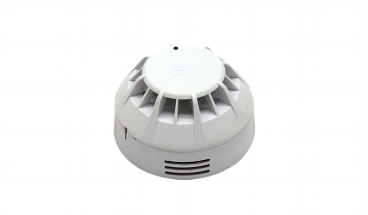
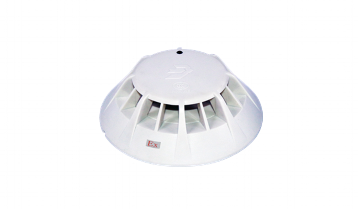
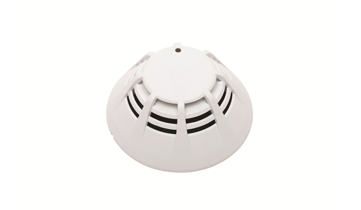
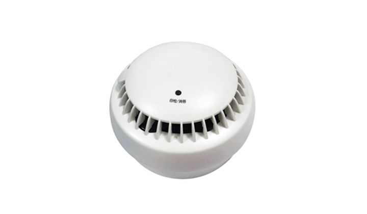
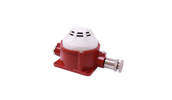
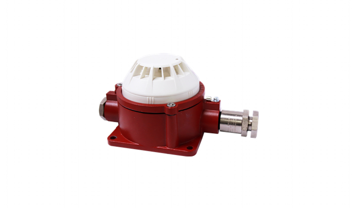
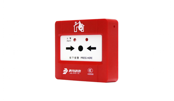
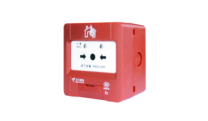
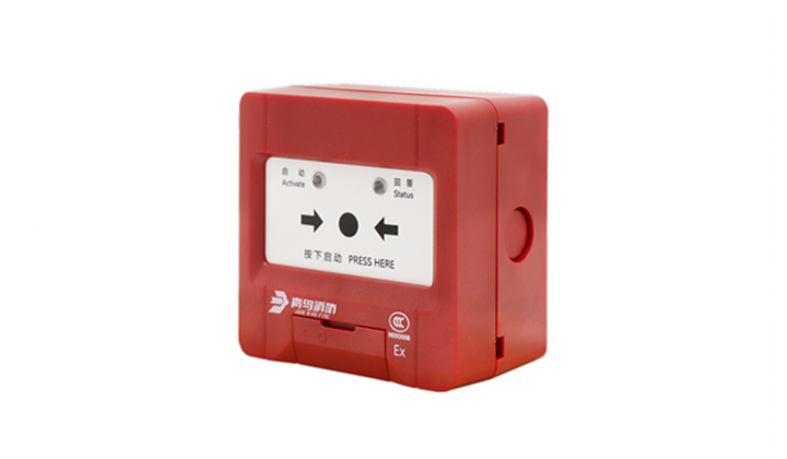
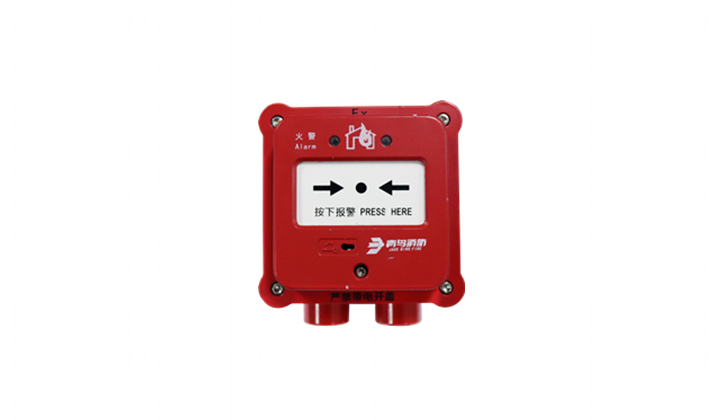
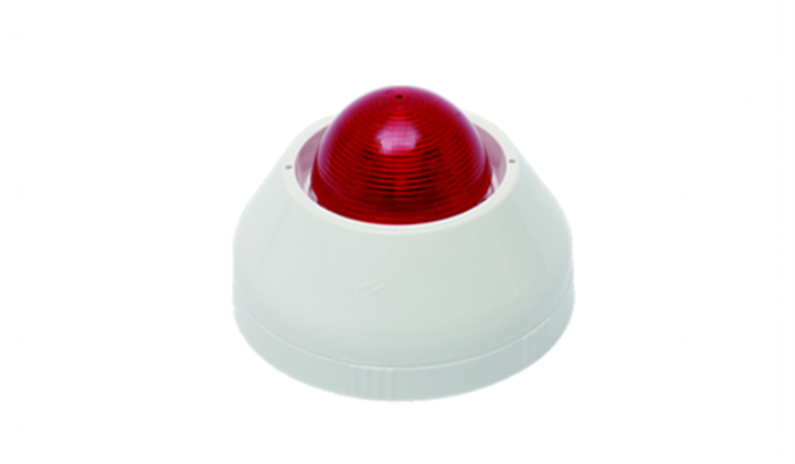
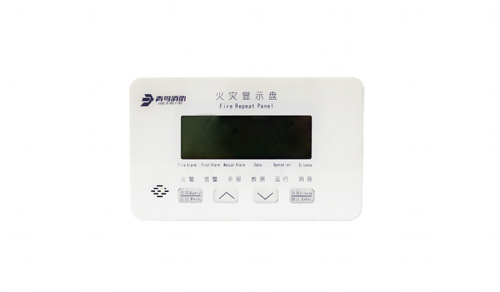
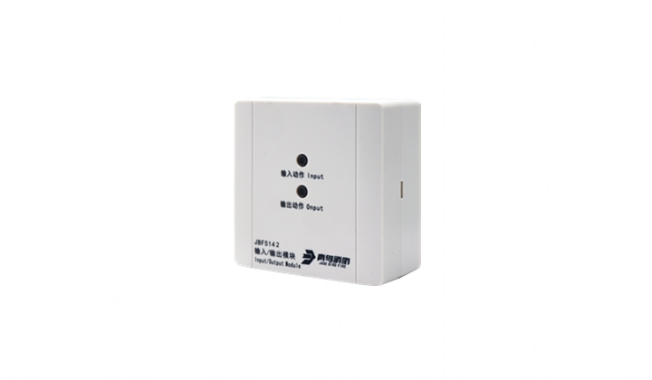
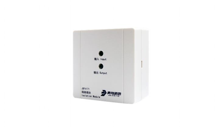
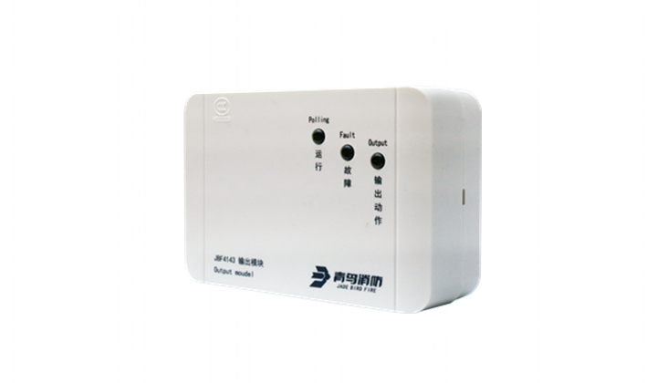
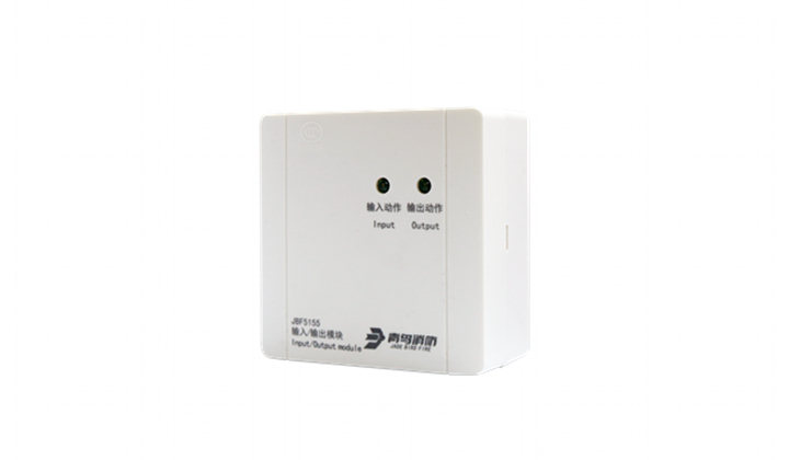
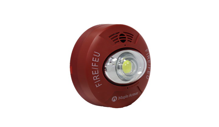
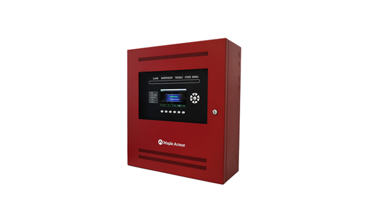
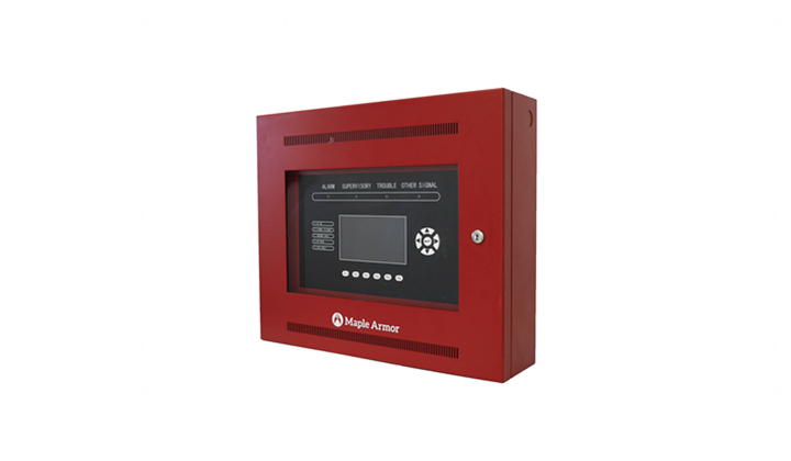
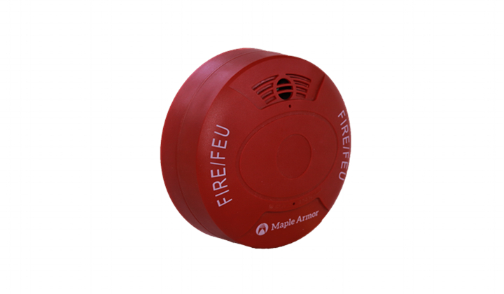
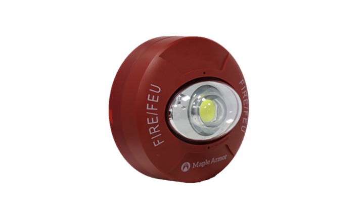
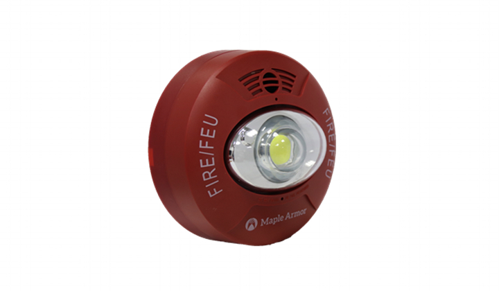
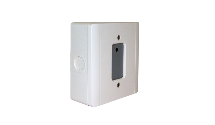
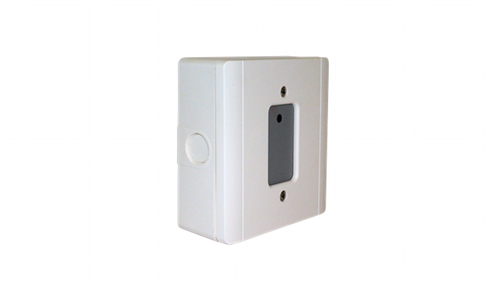
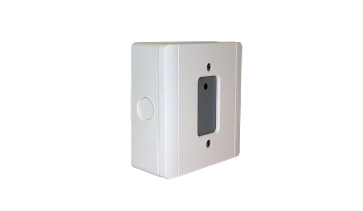
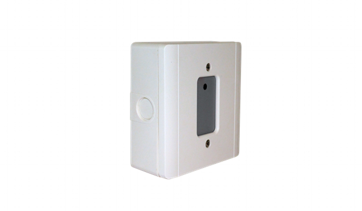
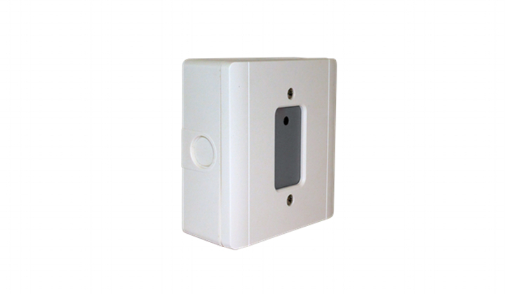
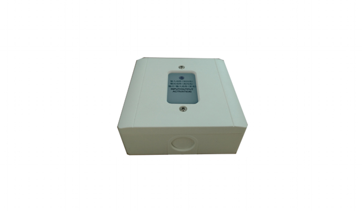
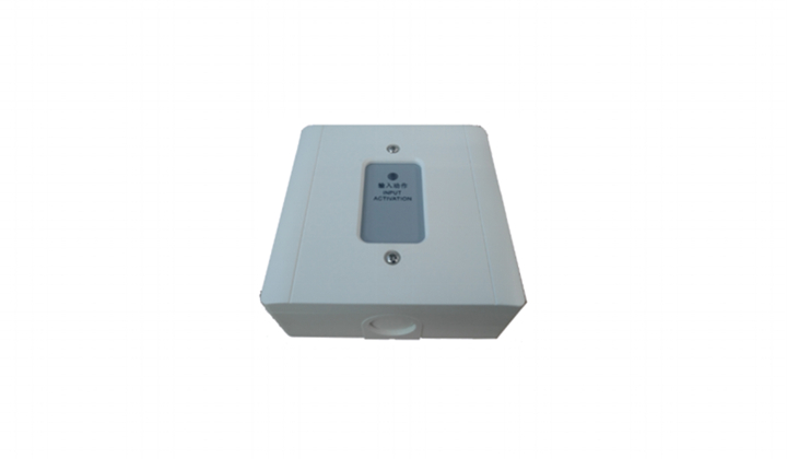
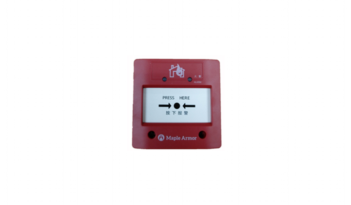
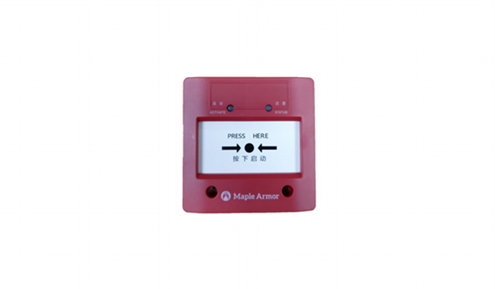
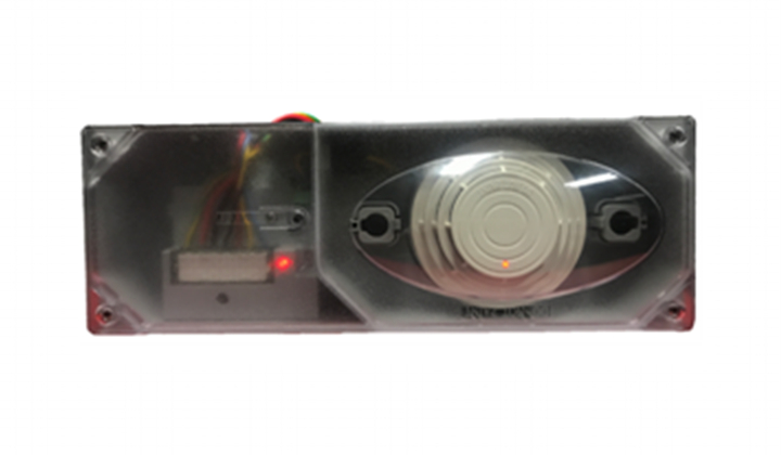
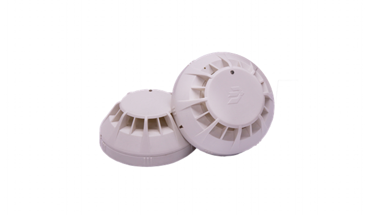
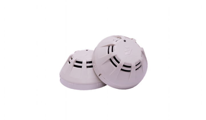
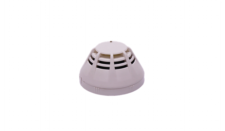
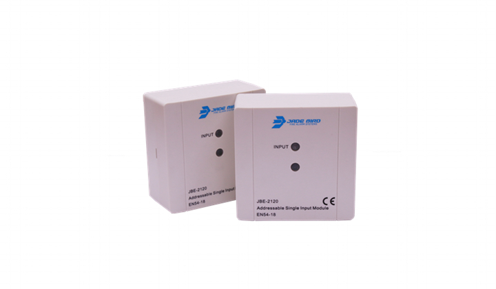
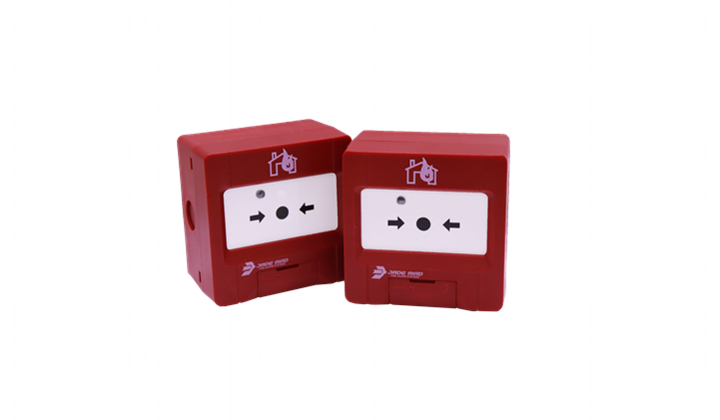
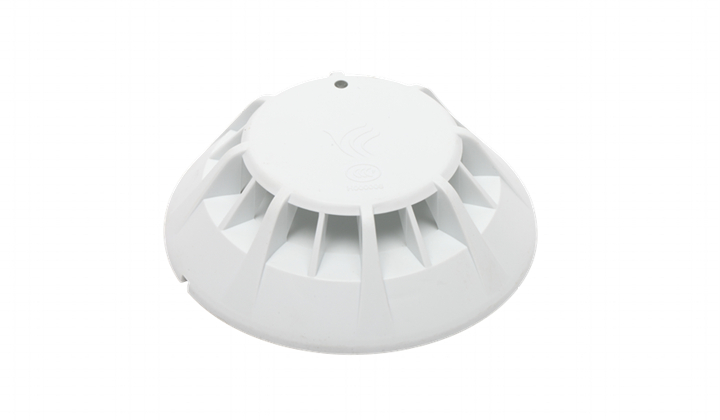
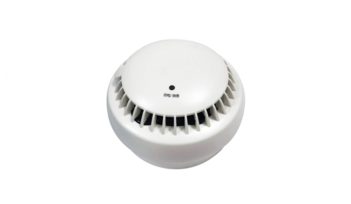
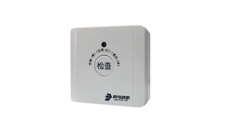
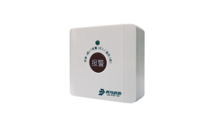
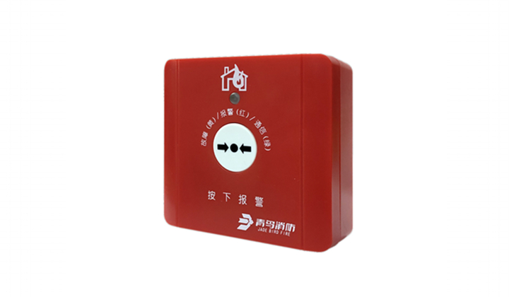
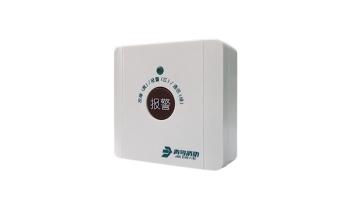
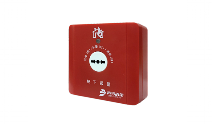
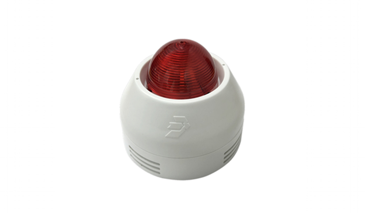
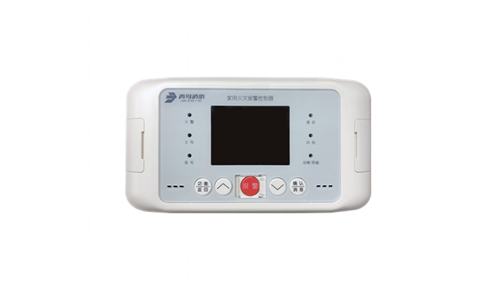
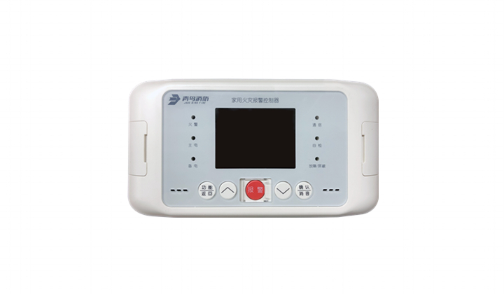
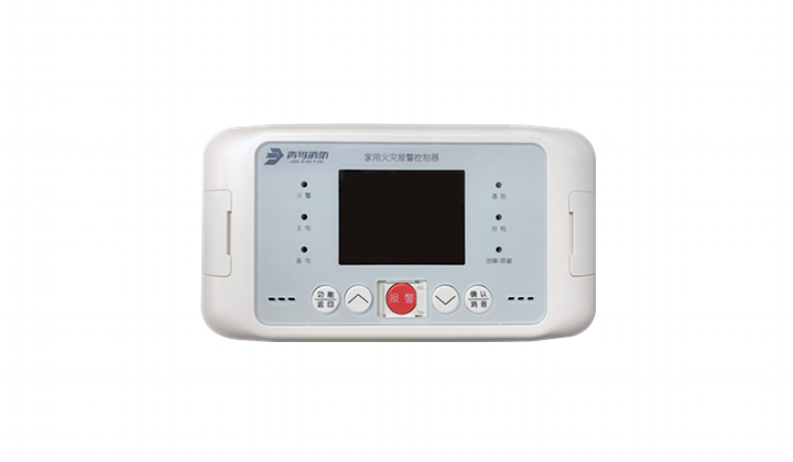
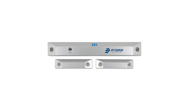
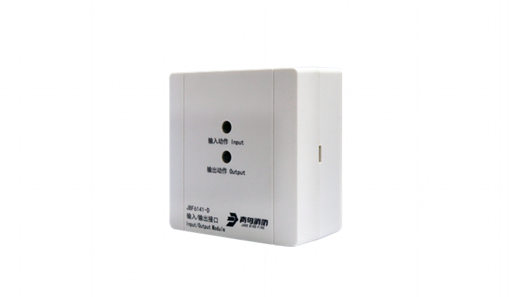
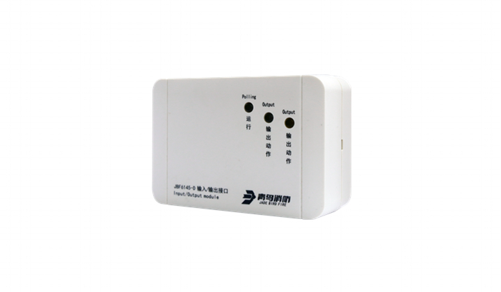
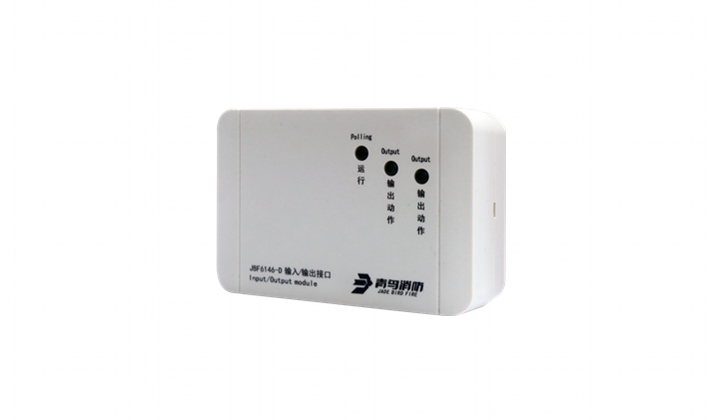
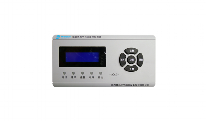
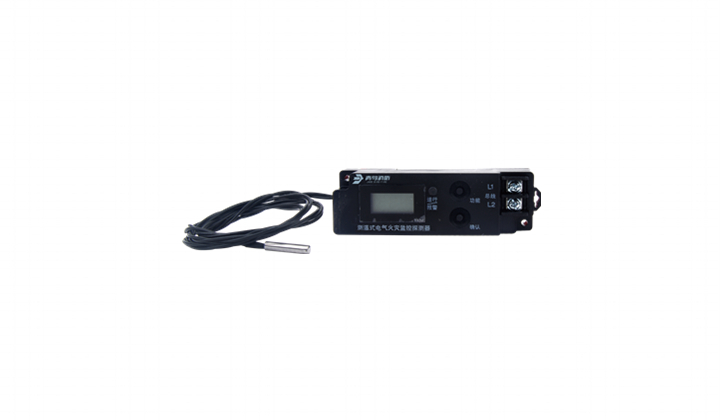
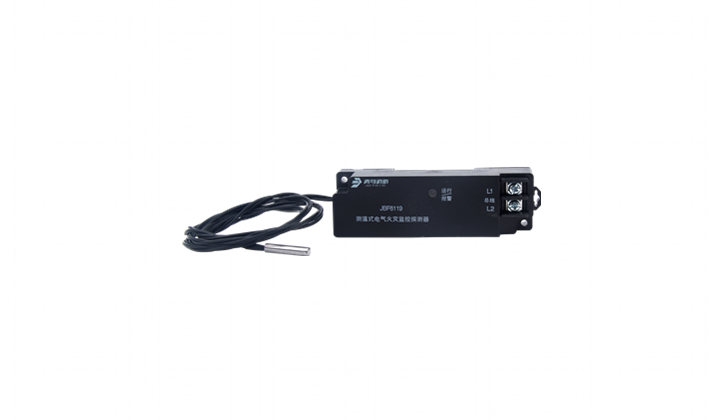
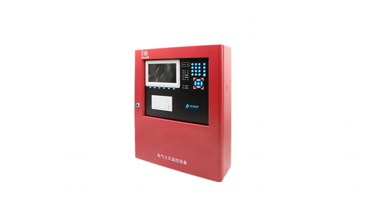
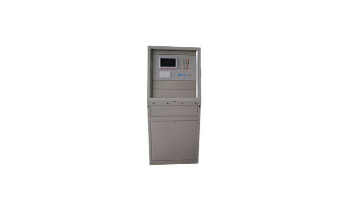
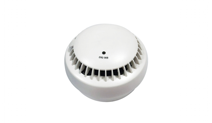
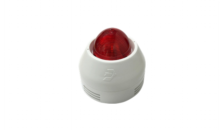
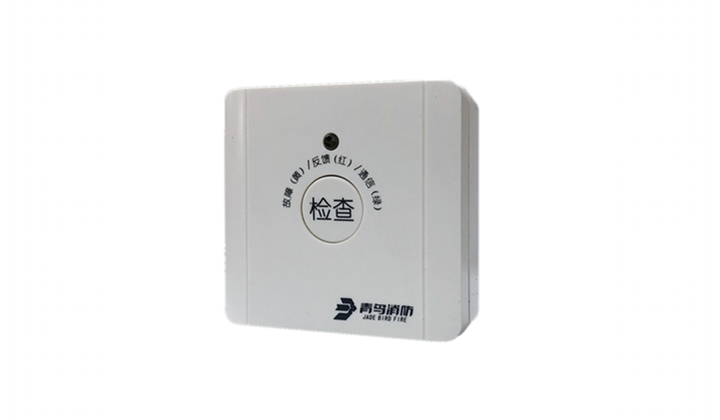
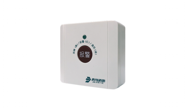
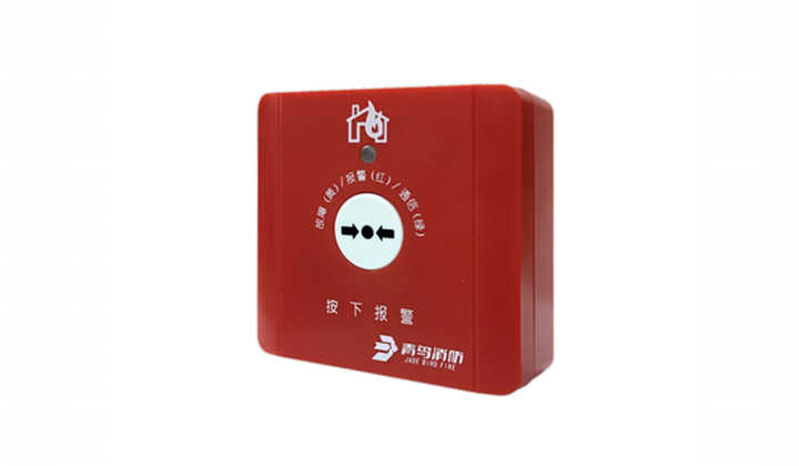
The hydrant button and JB series detectors are used together in the two-bus fire alarm system with the Jade Bird series control panels. It is used to manually send alarm, start fire pump and show the operation state of the fire pump when fire occurs in public places. Application design is in accordance with national standards GB 50116 "Fire automatic alarm system design specification." It is suitable for industrial and civil places where combustible and explosive gases existing.
Product Features
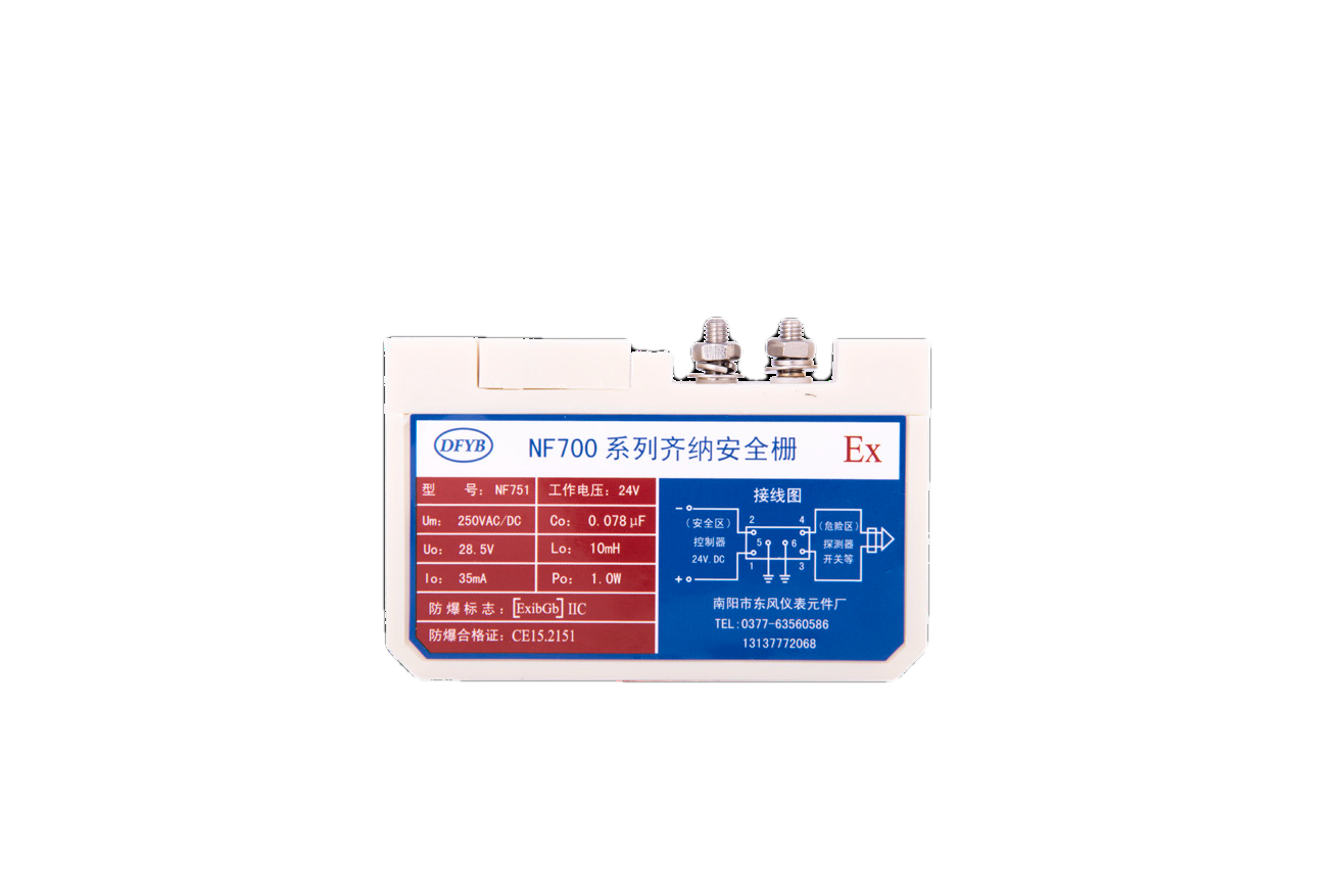
● Explosion proof is intrinsic safe type and requires use of safety barrier.
● With all functions of fire hydrant button.● Built-in microprocessor, performance is stable.
● Adopt SMT process, high reliability, good consistency.
● Two-bus system without polarity requirements, and the communication distance is up to the 1000m at a very low power consumption.
● Electronic addressing with specialized device.● With a plug-in structure, this button is easy to install, construct and maintain.● Explosion-proof performance is in accordance with GB 3836.1 2010 "explosive environment, part 1: general requirements for equipment", GB 3836.4 2010 "explosive environment part 4: "i" intrinsic safe protected devices", explosion-proof mark is ExibIICT6Gb, applicable zone 1 and 2 containing II A-II C, and sites that contain T1-T6 explosive gas mixture.● The relevant technical data, drawings and prototypes have been examined and tested by the national center for quality supervision, inspection and testing of explosion-proof electrical products (CQST).The certificate number is CNEx18.1924X.Technical Data
| Item | Parameters |
| Working voltage | DC 19-28V |
| Monitoring current | ≤0.3mA (24V) |
| Alarm current | ≤1mA (24V) |
| Explosion proof mark | Ex ib IIC T6 Gb |
| Contacts capacity | DC30V/0.1A |
| Addressing method | Electronic addressing |
| Address range | 1-200 |
| Indicators | Flashes in monitoring state, constant on (red light) when in alarm state. Constant on (green light) when pump activation acknowledge signal received. |
| Operating temperature | 0—+55℃ |
| Storage temperature | -30—+75℃ |
| Relative Humidity | ≤95%RH (40±2℃) |
| Dimensions | 90mm × 90mm × 52mm (L × W × H) |
| Wires | Two-wire bus, non-polarity |
| Weight | 160g |
Structure and Dimensions
1) After wiring construction, the base is secured to the wall by pre-buried box or using expansion bolts. The pitch of holes distance is 60mm (compatible with 50mm mounting holes distance).
2) The hydrant button adopts RVS2×1.5mm2 twisted pair connecting to the control panel.
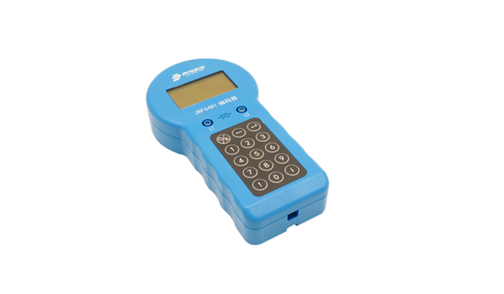
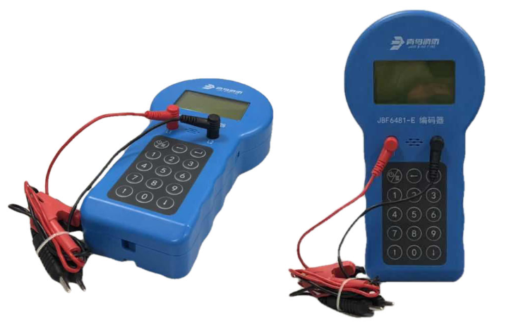
3) Write address (1-200) to the manual call point using electronic encoder.
4) The detection bus L1, L2 connect to terminal 1 and terminal 2.
5) There are knock-down holes in the left and right positions of the base (waterproof connector is required if the hole is used for entering cable). In normal installation, it is recommended to enter the cable from the bottom inlet hole, which can be without special waterproof sealing, easy to operate and convenient.
6) Fire hydrant button is recommended to be installed after wiring inspection and before commissioning to prevent losses caused by improper installation.
7) After checking the wiring, insert the fire hydrant button to its base and use tapping screws to secure them together. 
● Installation shall be carried out in accordance with the relevant provisions of GB 3836.15-2010 Electrical apparatus for explosive gas atmospheres - Part 15: Electrical installations in hazardous areas (other than mines) and by our company's professionals.
● The safety barrier shall obtain an explosion-proof certificate and its installation shall be carried out in accordance with the requirements of its instructions.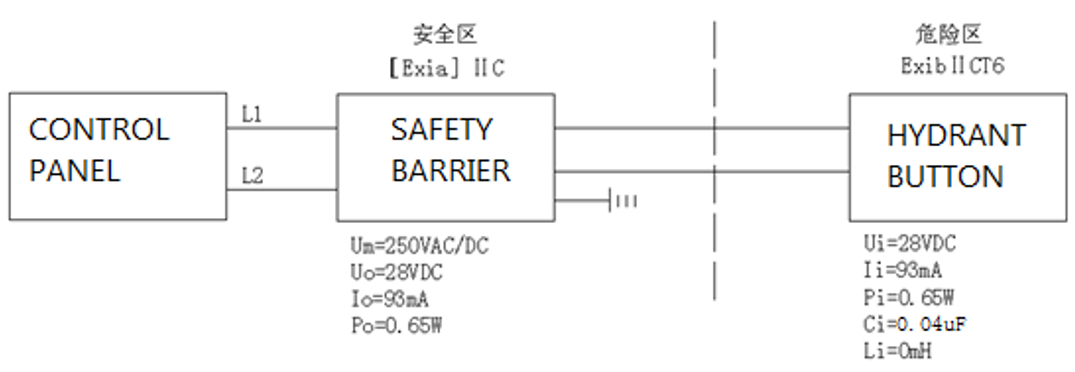
Uo ≤ Ui;Io ≤ Ii;Po ≤ Pi;Cc ≤ Co-Ci;Lc ≤ Lo-Li
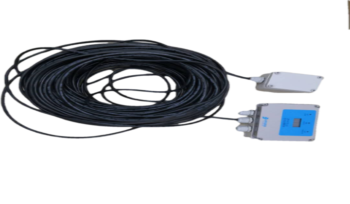
Cc, Lc: The maximum allowed cable (or wire) distribution capacitance and inductor between the safety barrier and the hydrant button. Uo: maximum output voltage of the safety barrier. Io: maximum output current of safety barrier. Po: maximum output power of safety barrier. Lo: maximum external inductor allowed by safety barrier. Co: maximum external capacitor allowed by the safety barrier. Ui: maximum input voltage of the hydrant button. Ii: maximum input current for the hydrant button. Pi: maximum input power of the hydrant button. Li: maximum internal inductor of the hydrant button. Ci: maximum internal capacitance of the hydrant button.
The detailed meaning of the symbol can be found in GB 3836.4-2010 standard.
Conduct alarm test regularly, every six months recommended.
Warning: potential static charge hazard. To avoid fire caused by static charge in normal use, maintenance and cleaning, do not touch or clean the manual call point in explosive environment. If the device must be cleaned, please wipe it with half wet cloth. Never wipe the outside with dry cloth.
