Tel:400 008 9119 Login  CN | EN

JBE-2115


Applied to EN standard. When ambient smoke concentration rises to the set threshold, the fire alarm signal is sent to the control panel
JBE-2115
Overview
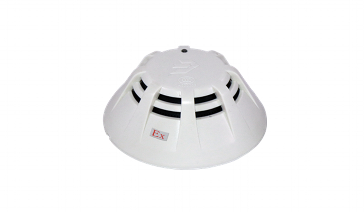
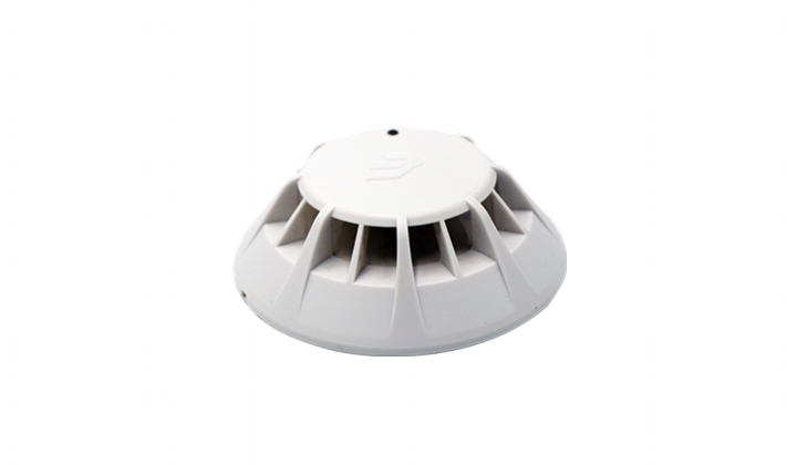
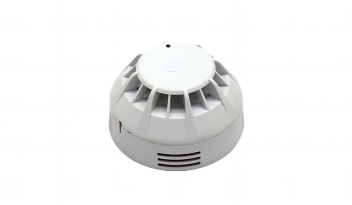
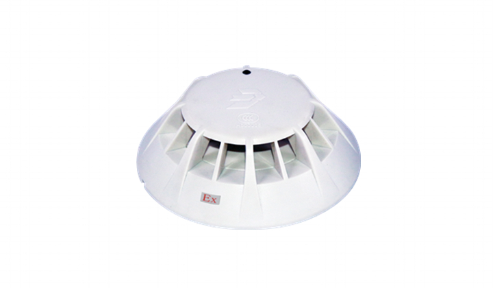
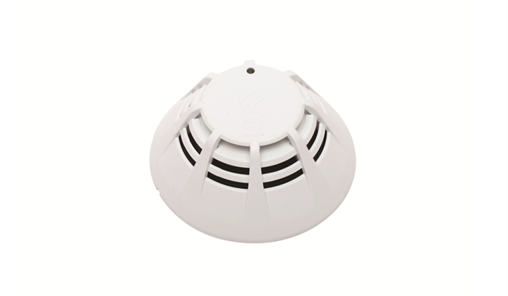
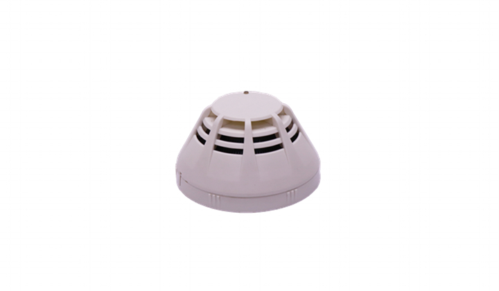
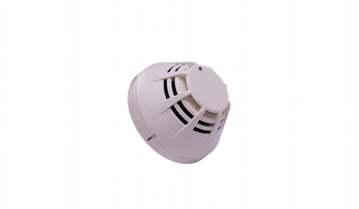
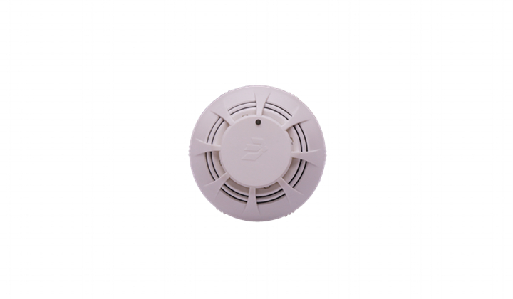
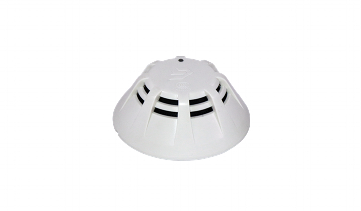
JBE-2115 is an addressable combined heat and optical smoke detector designed to operate on a loop of intelligent fire detection and alarm devices with the JBE loop protocol. It sends fire alarm signals to the fire panel when the pre-selected levels of heat or smoke are detected.
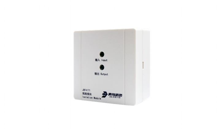
The detector features six (6) sensitivity profiles, which combine different levels of heat and smoke.
JBE-2115 has pollution compensation function that prevents false alarm results from dust accumulation.


Technical Data
CategoryEN 54-5 (A2 type) and/or EN 54-7 depending on the profile selection in the control panel.
Working voltageDC 19-28V (JBE protocol pulse amplitude)
Connection2-wire JBE communication bus, no polarity
WiringTwisted pair, max. wiring gauge 2.5 mm2
Quiescent current≤0.3mA @24V
Activation current≤1 mA @24V
Working temp-10℃ to +60℃
Storage temp-30℃ to +70℃
Environment Humidity≤ 95% RH (40±2℃) (no condensation nor icing)
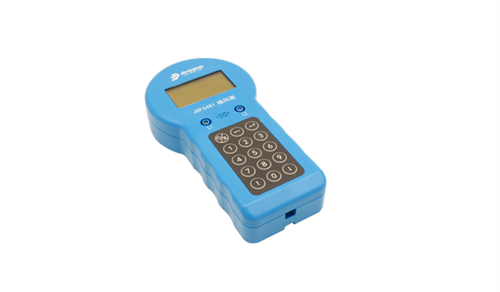
Addressing methodSoft addressing with tool JBE-AT1, non-volatile
Address range1-200
Protection area20~30m2 (subjected to local codes)
Red LED indicationFlashes when polling.Constant on when alarms.
DimensionØ100mm × 53 mm
Weight0.1 kg
IP ratingIP40
Compatible baseJBE-2160


Sensitivity levels
The detector performs continuously independent measurements of heat and smoke, allowing the fire panel to indicate alarm, depending on the selected alarm profile.
Each profile incorporates at least one EN 54 certified heat and/or smoke alarm levels. However, note that some profiles incorporate alarm levels which are above or below EN 54 requirements. Thresholds compliant to EN 54 are indicated in the table below. 

ProfileSensitivity smokeSensitivity heat
1Very highEN 54-5 A2
2EN 54-7EN 54-5 A2
3EN 54-7Very low
4EN 54-70 (no heat alarm)
5Very lowEN 54-5 A2
60 (no smoke alarm)EN 54-5 A2
 
Expert judgement is required in order to select the most appropriate profile for each application. Compliance to EN 54 requirements shall not be assumed for those profiles which are not indicated as such.
The day/night programming in the Draco fire panel allows changing automatically the profile at different times of the day or the week.

Installation
Always observe local fire and electric installation regulations.
1.Secure the base to the ceiling.The nominal spacing of drills is 60mm
2.Connect the wiring to the base:
TerminalsConnection
1 & 2Signal loop L1, L2(interchangeable: No polarity)
3.Program an unused loop address (1 to 200) to the detector head using the JBE-AT1 tool.
4.Mount the detector onto its base and turn it clockwise to secure.
5.Register the detector into the fire panel’s configuration. Select the sensitivity profile most appropriate for your application
6.Test each detector and wiring integrity after installation.

Mechanical dimensions

all dimensions in mm
Maintenance
Alarm test should be conducted regularly, recommending every 6 months.
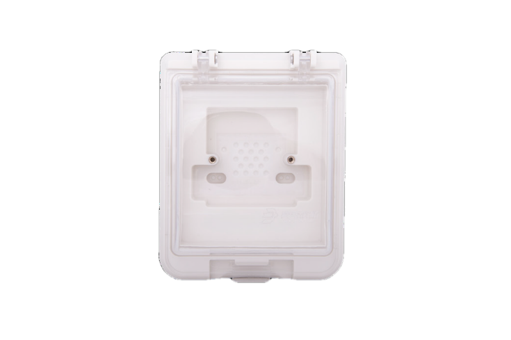
The dust cover can protect the detector from noxious dust accumulation during construction works, but the detector won’t be able to detect smoke while the dust cover is on!