Overview
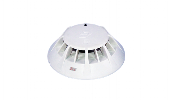
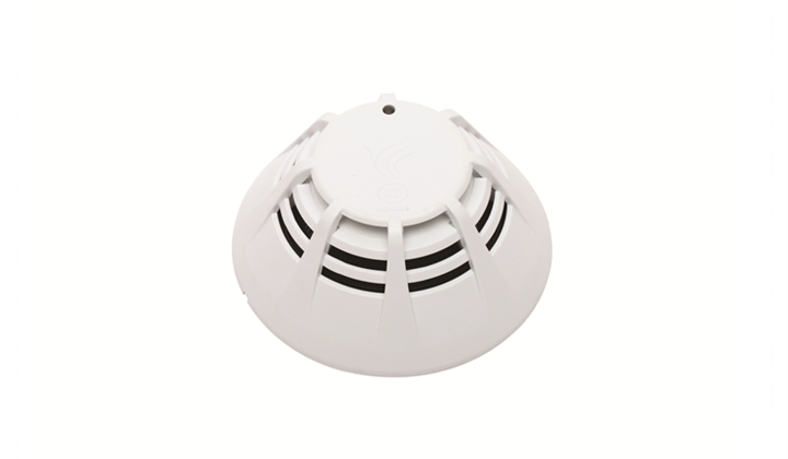
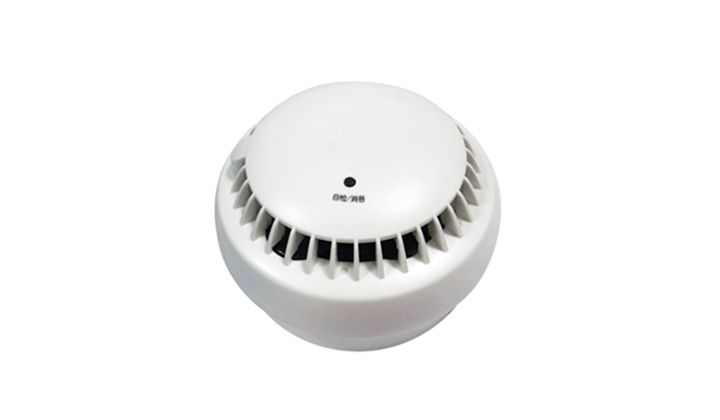
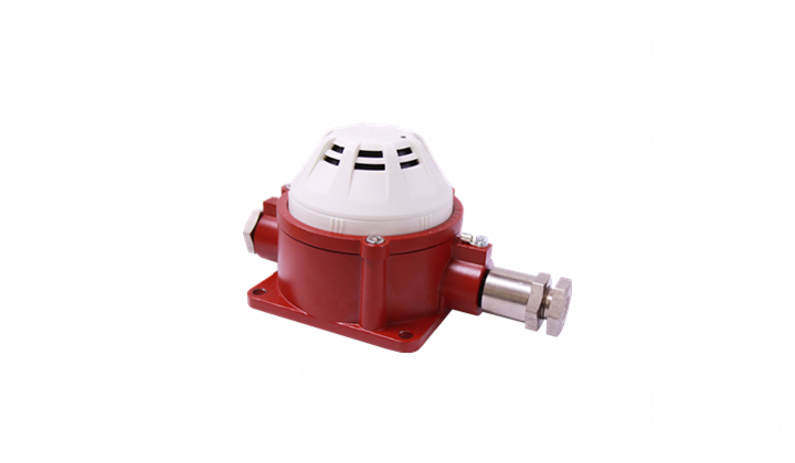
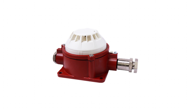
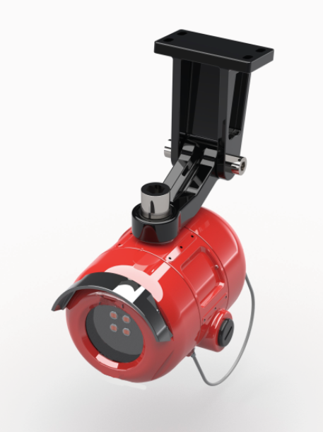
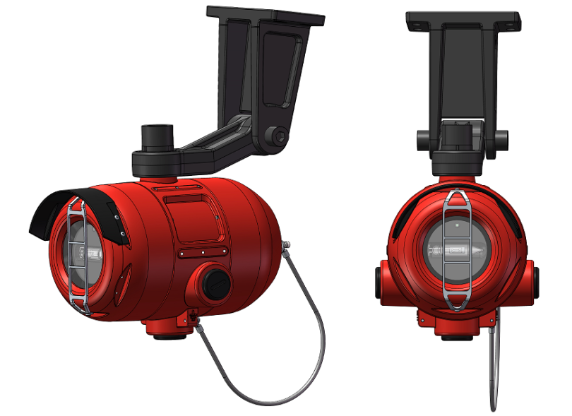
JTG-Z-JBF4385-Ex point type UV flame detector (hereinafter referred to as flame detector) using specially designed sun-blind UV sensor, and with the built-in high-speed microprocessor and advanced signal processing algorithm can effectively distinguish the real flame radiation and interference sources, improve alarm speed, and greatly reduce the impact of environmental factors. Detectors can set multiple levels of sensitivity to meet the needs of different situations. Excellent explosion-proof design ensures usage in harsh environment.
1.1 Product features
- The product is designed according to the requirements of industry standards, and the performance is stable and reliable.
- Three-color indicator can display normal working status, alarm status and fault status.
- Multi-level sensitivity is adjustable.
- Intelligent algorithm can not only realize fast alarm but also reduce false alarm rate.
- Fault mode can accurately locate the fault information.
- Automatic defrost function, better resistance to window condensation and frost in low temperature (Optional and select it when placing orders).
- Various output ports meet different application scenarios.
- Enclosure adopts High-strength die-cast aluminum and sapphire glass of high quality. Explosion-proof and the protection grade reaches IP67, with anti-dust, anti-moisture and the corrosion resistance characteristics.
- The relevant technical information, drawings and prototypes passed inspection by Supervision & Test Center of Ex-products of China Petroleum & Chemical Industry (PCEC) for electrical products.
- The flame detector has excellent anti-interference ability, and is not affected by wind and rain, high temperature, high humidity, natural artificial light source, lightning, etc., and can work well in various harsh industrial sites indoors or outdoors.
1.2Application scope
- The flame detector is mainly suitable for oil depots, alcohol depots, aircraft hangars, area with chemical equipment, liquefied gas stations and other flammable and explosive industrial fields, and places where there would be no or little smoldering stage, directly producing open flames.
- Flame detectors are suitable for Area 1 and 2 with combustible gases or explosive mixtures of dust and air that belonging to T1 ~ T6 Class II Grade A, B, C and Hazardous Area 21 and 22
Notes: This type of product is not suitable for situations where arc welding is conducted or there is radiation that responses to the ultraviolet band sensed.
1.3Model composition
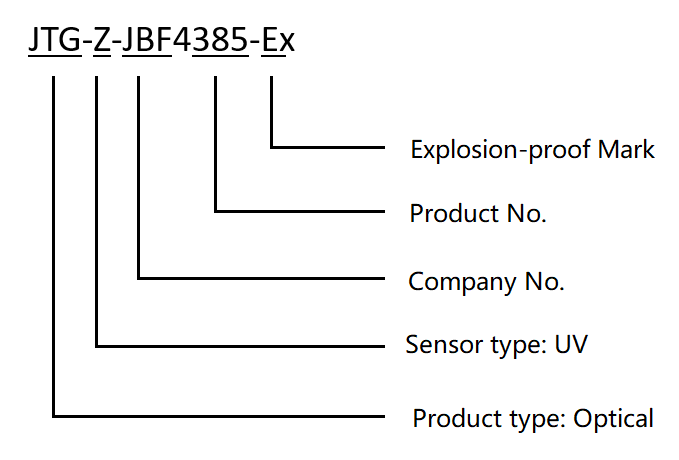
The point-type UV flame detector is a photosensitive fire detector that responds to 185nm-260nm UV light (sunshine blindness) in the flame radiation spectrum. The product relies on UV sensors to receive light from combustibles (combustibles that generally emit ultraviolet light when ignited are hydrocarbons, hydrogen, silane, hydrogen and metal fires) and detect flame.
Technical Data
Environment features
| Working temperature | -40~+75℃ |
| Storage temperature | -40~+85℃ |
| Relative humidity | ≤95% (no condensation) |
Explosion-proof features
| Explosion-proof mark | ExdⅡC T6 Gb/ExtDA21 IP67 T80℃ |
Electrical features
| Voltage | Rated voltage: DC24V
Working voltage: DC18~28V |
| Monitoring current | 17mA~27mA (DC24V) |
| Alarm current | 28mA~40mA (DC24V) |
Defrost current
(current) | 130mA~220mA (DC24V) *after the defrost function is activated* |
| Activation time | <1s |
| Indicator | Monitoring status green light flashing, alarm status red light solid, fault status yellow light solid. |
Communication features
| Outputs | 1) Three sets of dry node outputs (fire alarm relays, fault relays and auxiliary relays) with a 2A@30VDC relay contact capacity.
2) RS485 (Modbus Protocol, see “Flame Detector RS485 Application Manual)”
3) 4-20mA isolated output |
| Addressing range | NA |
| Addressing method | Not addressable |
| Max transmission distance | RS485 1000m |
Compatibility
| Through JBF4137A relay module to connect JBF-11SF series or JBF50XX series fire control panel |
Mechanical features
| Appearance | RAL3003 Ruby Red |
| Housing material | Die-casting aluminum |
| Protection rate | IP67 |
| Electrical interface | 3×M20×1.5mm |
| Product weight | 2.5kg (with installation bracket) |
| Dimensions | L 133mm × W130mm × H182mm (without installation bracket) |
Detection features
| Protection area | Refer to 3.1 |
| Response time | ≤5s |
| Alarm threshold | Low, medium and high 3 adjustable level (factory default settings: medium)
The number of times each green light flashes in the monitoring status indicates the alarm threshold level.
The green light flashes 1 time low, 2 times medium, and 3 times high.
(The detection performance is best when the alarm threshold is low, but the false positive rate increases. When the alarm threshold is high, vice versa) |
| Alarm delay | 0-30s adjustable (factory default is 0 second) |
Certification
| Fire certification, Explosion-proof certification |
Applied standard
| 1) | GB 12791-2006 Point type ultraviolet flame detectors |
| 2) | GB 3836.1-2010 Explosive atmospheres - Part 1: Equipment-General requirements |
| 3) | GB 3836.2-2010 Explosive atmospheres - Part 2: Equipment protection by flameproof enclosures “d”. |
| 4) | GB 12476.1-2013 “Electrical apparatus for use in the presence of combustible dust - Part 1: General requirements” |
| 5) | GB 12476.5-2013 Electrical apparatus for use in the presence of combustible dust - Part 5: Protection by enclosures "D" |
Protection area
View range: 120 degrees; Sensitivity level: Level I.

Detection area schematic (horizontal direction) Detection area diagram (vertical direction)
| Source of Ignition | Max. detection distance |
| Combustible material | Ignition area |
| Normal Heptane | 0.1m2(0.3m×0.3m) | 40m |
| Ethanol. | 0.1m2(0.3m×0.3m) | 30m |
| Methanol. | 0.1m2(0.3m×0.3m) | 15m |
| Gasoline. | 0.1m2(0.3m×0.3m) | 27m |
| Diesel. | 0.1m2(0.3m×0.3m) | 20m |
| Kerosene. | 0.1m2(0.3m×0.3m) | 20m |
| Methane. | 0.5m(L)×0.2m(W) | 20m |
| Hydrogen. | 0.5m(L)×0.2m(W) | 25m |
| Ammonia. | 0.5m(L)×0.2m(W) | 25m |
| Silane | 0.5m(L)×0.2m(W) | 15m |
| Office Paper. | 0.1m2(0.3m×0.3m) | 15m |
Installation and Commissioning.
Installation instructions/steps.
3.1 Installation instructions/steps.Warning: Always switch off the power supply of the cable before installing the flame detector.
Attention:
1. On-site installation, according to GB/T 3836.15-2017 standard requirements, use high-temperature cable, cable introduction device and plug with explosion-proof certificate that suits the environment.
2. The setting of the flame detector should follow “Code for design of automatic fire alarm system” (GB 50116) and other relevant specifications for implementation.
3. All connections should use cables of cross-section no less than 1.0 mm
2. The end should peel off about 6 mm of the insulation sheath, and connect to the terminals of JTG-Z-JBF4385-Ex flame detector.
4. Check whether the external cable is short-circuit or open.
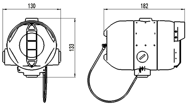
Dimensions
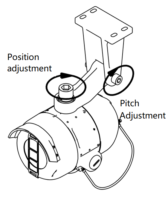
Ceiling-mounted
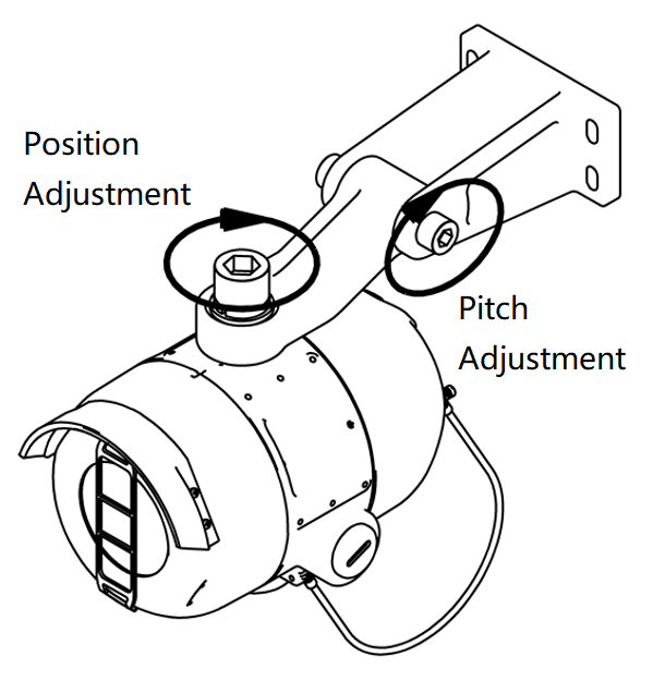
Wall-mounted
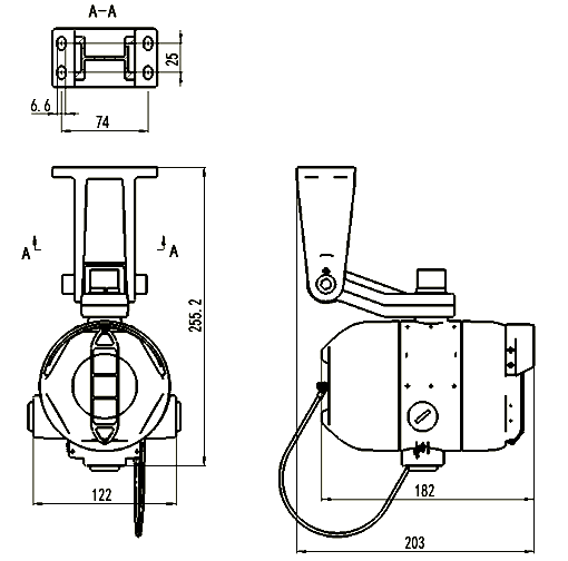
Front view Side view
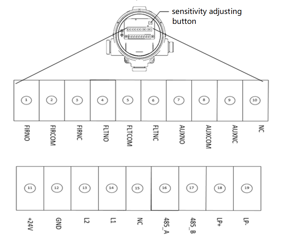
Figure 1 Terminals
| NO. | Name | Description |
| 1 | FIRNO | Fire relay contacts are normally open, closed when the fire detector reports fire alarm. |
| 2 | FIRCOM | Fire relay common contacts |
| 3 | FIRNC | Fire relay contacts are normally closed, and the contacts are open when the fire detector reports fire alarm. |
| 4 | FLTNO | Normally open relay; the contacts are closed when powered on. The contacts are open when the detector has fault. If the detector reports fire alarm at this time, the contacts remain open. |
| 5 | FLTCOM | Fault relay common contacts |
| 6 | FLTNC | Normally closed relay; the contacts are open when powered on. The contacts are closed when the detector has fault. If the detector reports fire at this time, the contacts remain closed. |
| 7 | AUXNO | Auxiliary relay, normally open, contacts closed when flame detector reports fire. 1 |
| 8 | AUXCOM | Common terminal of auxiliary relay 1 |
| 9 | AUXNC | Normally closed auxiliary relay; the contacts are disconnected when the flame detector reports fire. 1 |
| 10 | NC | Empty pin |
| 11 | +24V | DC 24V power input, polarity-free |
| 12 | GND | DC 24V power input, polarity-free |
| 13 | L2 | Fire bus loop L2 , polarity-free (this product is not addressable) |
| 14 | L1 | Fire bus loop L1 , polarity-free (this product is not addressable) |
| 15 | NC | Empty pins |
| 16 | 485_A | RS485 Loop A,RS485+ |
| 17 | 485_B | RS485 Loop B,RS485- |
| 18 | LP+ | 4-20mA current loop + |
| 19 | LP- | 4-20mA current loop |
Note 1: The auxiliary relay is connected according to the actual needs of customers, and it can provide voltage-free normally open / normally closed contacts with the capacity of 2A@30VDC. External devices or loads should not exceed the contact capacity of the auxiliary relay.
Form 1 Terminal description
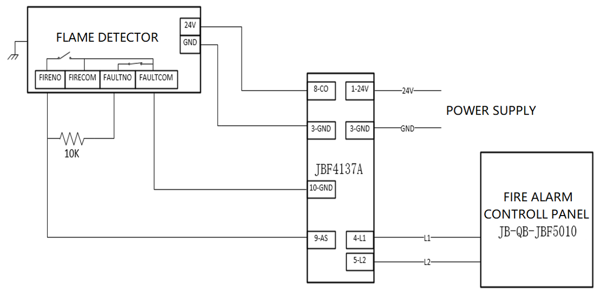 Figure 2 Flame detector and JB-QB-JBF5010 diagram
Figure 3 Flame detector and PLC wiring diagram
Commissioning
- Commissioning method for connecting fire alarm control panel.
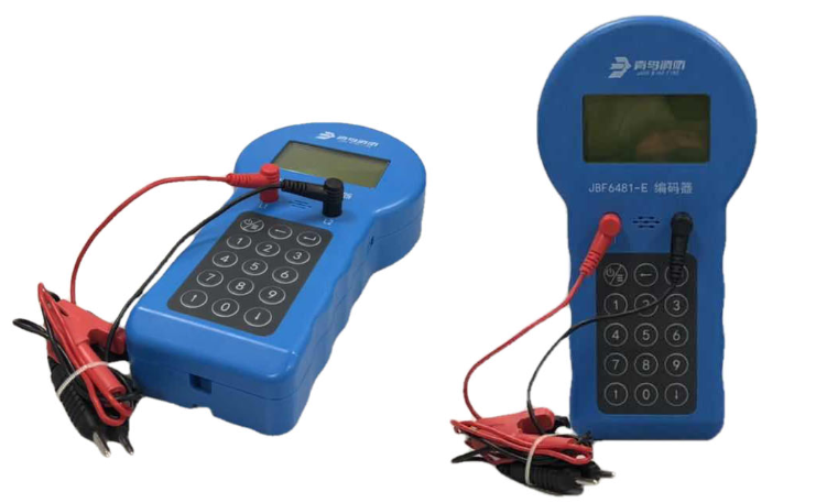
- Address JBF4137A relay module using electronic encoder.
- Complete the wiring following Figure 2. Register the module on fire alarm control panel.
- In front of the flame detector window, move the fire source or the simulated fire source. The flame detector should give fire alarm and the control panel should show fire information.
- Reset the fire alarm control panel, and the flame detector should restore normal monitoring status.
- Commissioning method for connecting industrial control machine PLC.
- Follow figure 3 to complete the wiring, and complete the settings on the PLC.
(Fault: 5mA, 5%; Normal: 10mA-5%; Alarm: 15mA-5%)
- In front of the flame detector window, move the fire source or the simulated fire source. The flame detector should give fire alarm and the PLC show fire information.
- Through the industrial control machine, cut off the flame detector DC24V power for 2s, and then re-power, the flame detector should restore normal monitoring status.
Troubleshooting
| Fault Phenomenon | Cause Analysis | Solutions |
| The patrol light is off, and fault is reported | 1. The power cord is not connected | Check and connect the power cable |
| 2. Poor contact | Rewire |
| 3. Wiring error | Check and connect the cable correctly according to the wiring diagram of the terminals |
| No output signal after flame detector alarms | 1. The output cable is not connected properly | Check the output cable and connect it correctly according to the wiring diagram |
| 2. The output cable is wear off or open |
| Flame detector frequently reports false alarms after powered-on | 1. On-site environmental impact | Clear the interference sources in surrounding environment |
| 2. There is problem with the sensitivity setting | Adjust the sensitivity according to the actual situation on site |
Maintenance.
- The grounding must be reliable.
- Do not change any components or structure of the product, so as not to affect the explosion-proof performance.
- During maintenance, take care of the explosion-proof surface. The surface must not be damaged or rusted.
- Do not open the product when it is powered on. Non-professionals are not allowed to install or disassemble the product.
- Flame detectors must be regularly tested and maintained in accordance with national standards and their relevant regulatory requirements. Clean the product at least once a year. Test the product once a month.
Out-of-box Check
After opening the package, this product should include:
| JTG-Z-JBF4385-Ex flame detector | ×1 |
| Manual | ×1 |
| Installation bracket | ×2 |
Accessory:
Inner hexagonal cylindrical head screw M16×35 ×1 (Used to connect product and installation brackets)
Inner hexagonal cylindrical head screw M10×16 ×2 (Used to fix the installation brackets)
Inner hexagonal flat head screw M6×8 ×1 (Used to fix the installation brackets)
Spring washer 16 ×1 (Used to fix the installation brackets with the product)
Flat washer 16 ×1 (Used to fix the installation brackets with the product) 10PIN terminal block ×1 (Used to output / provide power to external devices)
9PIN terminal block ×1 (Used to output / provide power to external devices) | ×1 |
If any item is missing or damaged, please contact us as soon as possible. We will immediately complete the missing item, or unconditionally replace with new product if it is determined caused by non-human factors.
Precautions, disclaimers.
- Auxiliary relays are connected according to the actual needs of the customer and can provide volt-free open/normally closed contacts with 2A@30VDC contact capacity, and external other equipment or loads should not exceed the auxiliary relay contact capacity.
- Explosion-proof cable introductions and plug need to be purchased separately and their explosion-proof rating should meet the ExdII C T6 Gb/ExtDA21 IP67 T80 C requirements.
- Please strictly follow the description of this manual for installation and commissioning.
- The Company reserves the right to finally interpret this specification.
