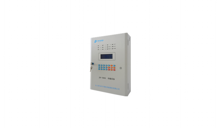
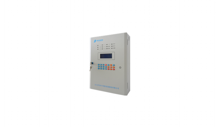
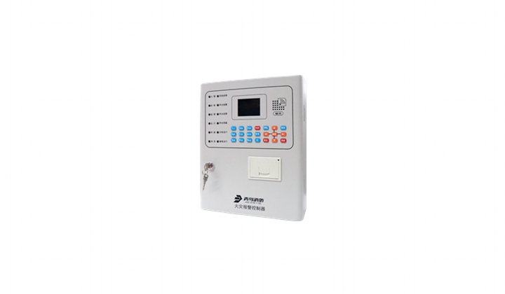
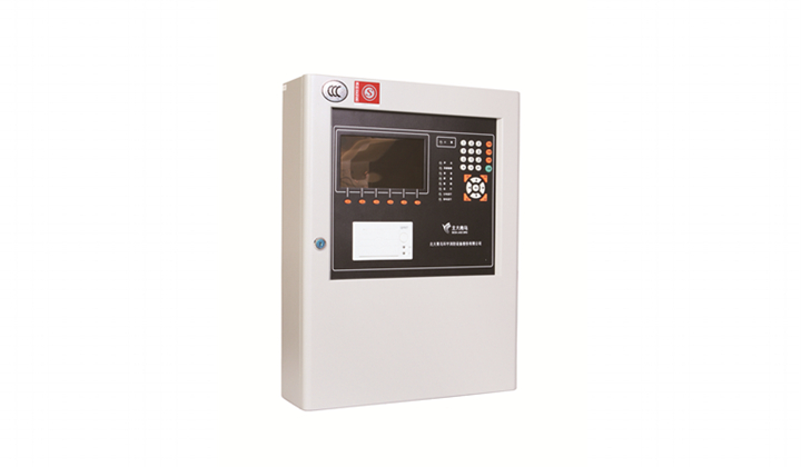
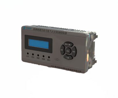
JBF-TD803
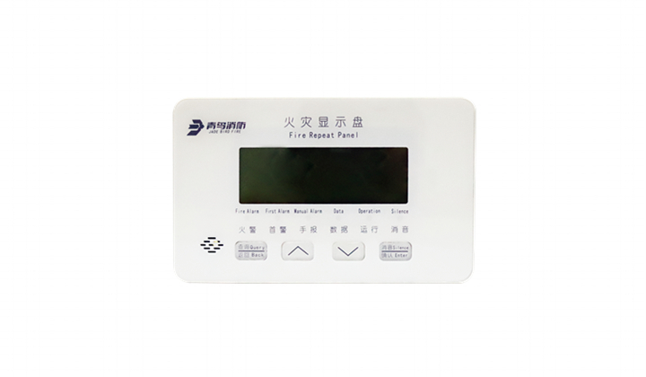
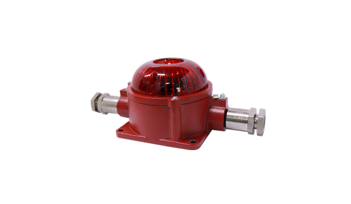
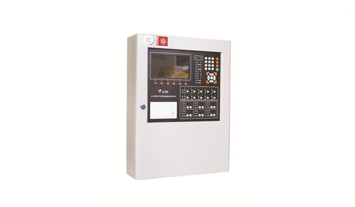
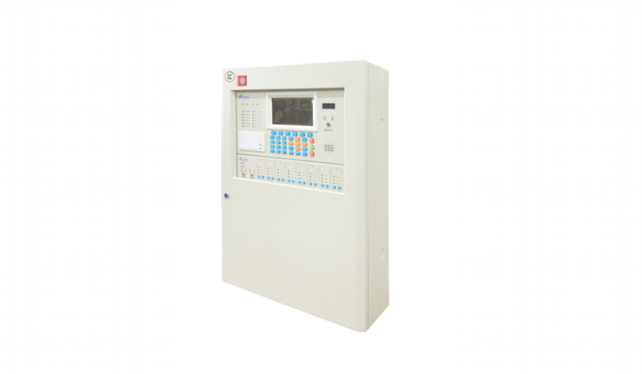
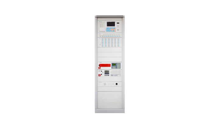
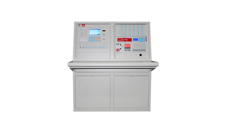
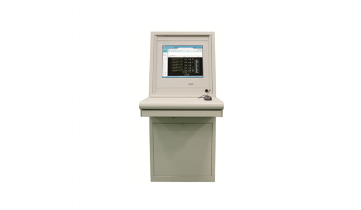
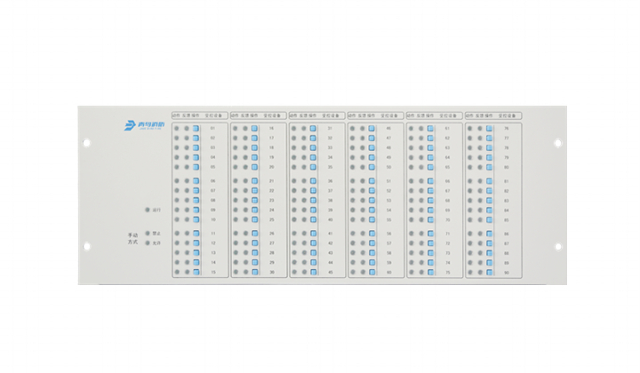
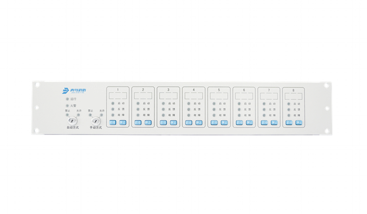
Connect with fire alarm control panelor fire alarm control panel (automatic) or other alarm equipment, used in small and medium-sized places, computer rooms, libraries and other places needing remote fire monitoring.













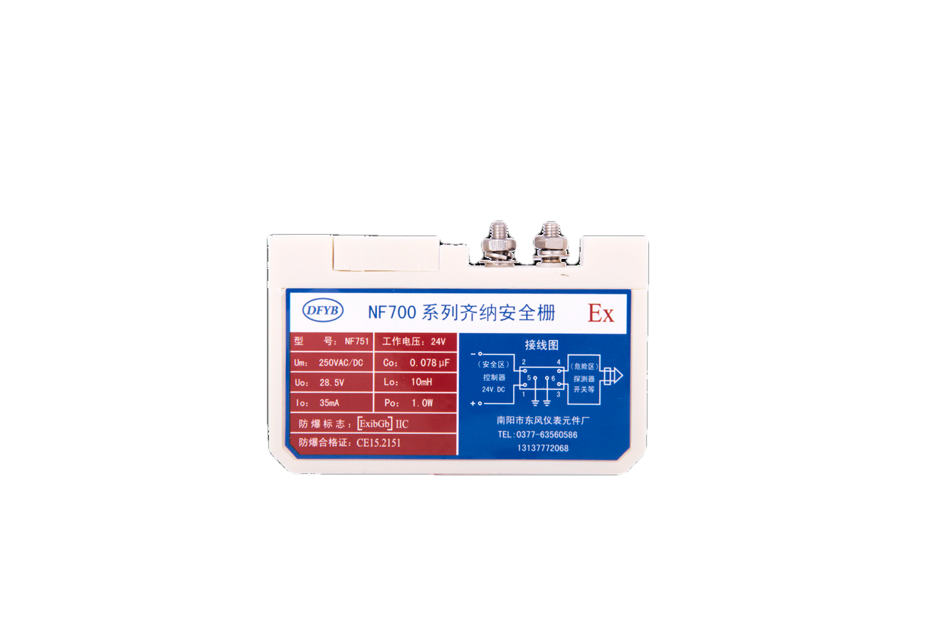

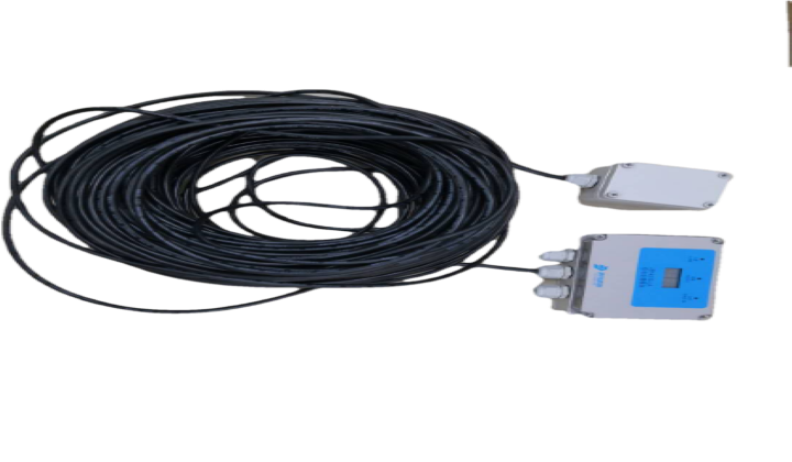
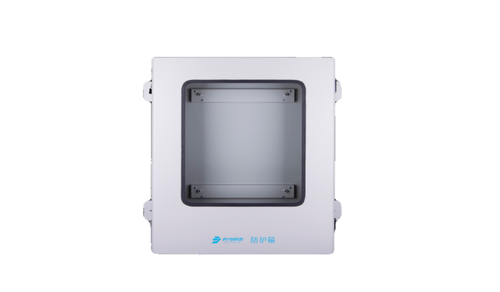


| Item | Technical parameters |
| Main power | AC187~242V, 50Hz |
| Standby power | DC12V, 4Ah |
| Input capacity | 2 sets of voltage-free input with test functions (must connect to EOLR RJ14-0.25W-5%-10K) |
| Output capacity | 2sets of DC12V 200mAvoltage output (dedicated for drive relay of DC12V, the internal resistance 200Ω-2KΩ) DC12V 200mA (dedicated for internal module of DC512V) DC5V 1A (dedicated for internal module of DC5V) |
| Operating temperature | 0…+40℃ |
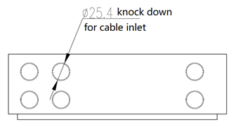
| Wire | RS232 (3-core) length≤15m; TCP/IP (standard net cable) length≤50m |
| Connected equipment | JB-QB-JBF5010 JB-QB-JBF5014 JB-TG-JBF-11SF JB-TT-JBF-11SF JB-TB-JBF-11SF-S JB-TB-JBF-11SF-S8 |
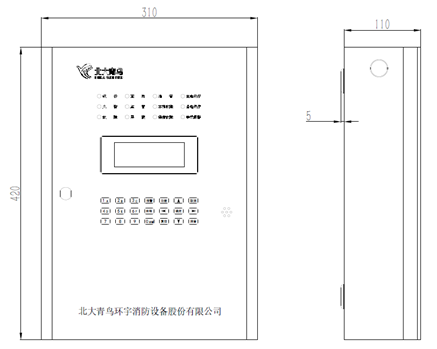
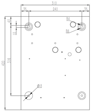
| Dimensions | 310mm×110mm×420mm |
| Weight | 6.9Kg |
| Installation | Wall-mounted |
| Applied standards | GB 26875.1-2011 |

| Terminals | Descriptions |
| +12V, G-12 | Drive output, power to internal module, distinguishing polarity; |
| DC+5V,G-5 | Drive output, power to internal module, distinguishing polarity; |
| R1_+12V, R1_GND | Voltage output 1, for driving relay(DC12V, internal resistance:200-2KΩ) |
| R2_+12V, R2_GND | Voltage output 2, for driving relay(DC12V, internal resistance:200-2KΩ) |
| NC | Reserved terminal |
| INPUT1+, INPUT1- | Imput terminal 1, for volt-free signal, connect to 10K, 1/4W 5%EOLR |
| INPUT2+, INPUT2- | Imput terminal 2, for volt-free signal, connect to10K, 1/4W 5%EOLR |
| TX1, RX1, SGND | Connect to ports of fire alarm control panel: RS232 serial port,TX1:RS232send,RX1:RS232receive S, GND:RS232 grounding; |
| TX2, RX2, SGND | System debugging serial port |
