

| Working temperature | -40~+75℃ |
| Storage temperature | -40~+85℃ |
| Relative humidity | ≤95% (no condensation) |
| Explosion-proof mark | ExdⅡC T6 Gb/ExtDA21 IP67 T80℃ |
| Working voltage | Rated voltage: DC24V Working voltage: DC18~28V |
| Monitoring current | 17mA~27mA (DC24V) |
| Alarm current | 28mA~40mA (DC24V) |
| Defrost function (Selectable) | 130mA~220mA (DC24V) *after the function gest activated |
| Activation time | 30sec. (system check) |
| Indicator | Green light flashes when monitoring; red light steady on when alarms, yellow light steady on when faults. |
| Output methods | 1) Three sets of dry node outputs (fire relays, fault relays and auxiliary relays), relay contact capacity 2A@30VDC. 2) RS485 (Modbus Protocol, see "The Flame Detector RS485 Application Manual”) 3) 4-20mA isolated output. |
| Address range | NA |
| Address method | Not addressable |
| Maximum transferring distance | RS485 communication 1000m |
| Connect to 11SF series and JBF50XX series control panel by relay module JBF4137A |
| Appearance | RAL3003 ruby |
| Housing material | die-casting aluminum |
| Protection grade | IP67 |
| Electrical interface | 3×M20×1.5mm |
| Product weight | 2.5kg (with installation brackets) |
| Dimensions | L 133mm × W130mm × H182 mm (without installation brackets) |
| Protection area | Refer to 3.1 |
| Response time | ≤5s |
| Alarm threshold | Low, medium and high 3 adjustable levels (factory default setting is medium) The number of flashing times of the green light of the monitoring status indicates the alarm threshold level. Low: 1 time; medium: 2 times; high: 3 times. (The detection performance is best when the alarm threshold is low, but the false positive rate increases, and when the alarm threshold is high, the reverse) |
| Alarm delay | 0-30s settable (default is 0s) |
| Fire protection certificate, explosion-proof certificate |
| 1) | GB 15631-2008 “Special type fire detectors” |
| 2) | GB 3836.1-2010 “Explosive atmospheres - Part 1: Equipment-General requirements” |
| 3) | GB 3836.2-2010 “Explosive atmospheres - Part 2: Equipment protection by flameproof enclosures “d”. |
| 4) | GB 12476.1-2013 “Electrical apparatus for use in the presence of combustible dust - Part 1: General requirements” |
| 5) | GB 12476.5-2013 “Electrical apparatus for use in the presence of combustible dust - Part 5: Protection by enclosures "tD" |

| Ignition | Maximum distance | |
| Combustible | Ignition size | |
| n-heptane | 0.1m2(0.3m×0.3m) | 60m |
| Ethanol. | 0.1m2(0.3m×0.3m) | 40m |
| Methanol. | 0.1m2(0.3m×0.3m) | 20m |
| Gasoline. | 0.1m2(0.3m×0.3m) | 50m |
| Diesel. | 0.1m2(0.3m×0.3m) | 45m |
| Kerosene. | 0.1m2(0.3m×0.3m) | 45m |
| Methane. | 0.5m(L)×0.2m(W) | 40m |
| Hydrogen. | 0.5m(L)×0.2m(W) | 30m |
| Ammonia. | 0.5m(L)×0.2m(W) | 30m |
| Silane. | 0.5m(L)×0.2m(W) | 25m |
| Office paper. | 0.1m2(0.3m×0.3m) | 30m |


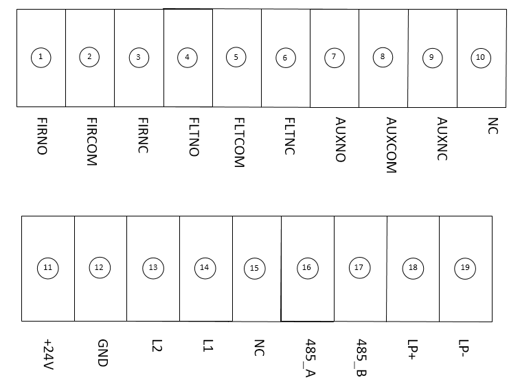
| No. | Name | Description |
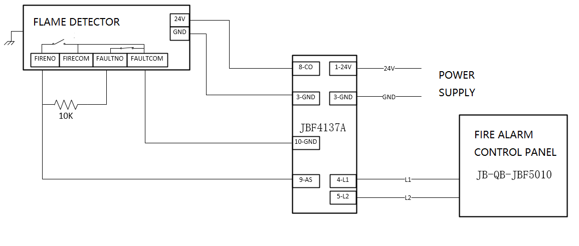
| 1 | FIRNO | Fire normally open relay; the contact is closed when the flame detector reports fire alarm |
| 2 | FIRCOM | Common terminal of fire alarm relay |
| 3 | FIRNC | Fire normally closed relay; the contact is open when the flame detector reports fire alarm |
| 4 | FLTNO | Fault normally open relay; the contact is closed when powered on. The contact is open when the detector has fault. If the detector reports fire alarm at this time, the contact remains open. |
| 5 | FLTCOM | Common terminal of fault relay |
| 6 | FLTNC | Fault normally closed relay; the contact is open when powered on. The contact is closed when the detector has fault. If the detector reports fire at this time, the contact remains closed |
| 7 | AUXNO | Auxiliary relay, normally open, contact closed when flame detector reports fire. 1 |
| 8 | AUXCOM | Common terminal of auxiliary relay 1 |
| 9 | AUXNC | Normally closed auxiliary relay; the contact is disconnected when the flame detector reports fire. 1 |
| 10 | NC | Empty pin |
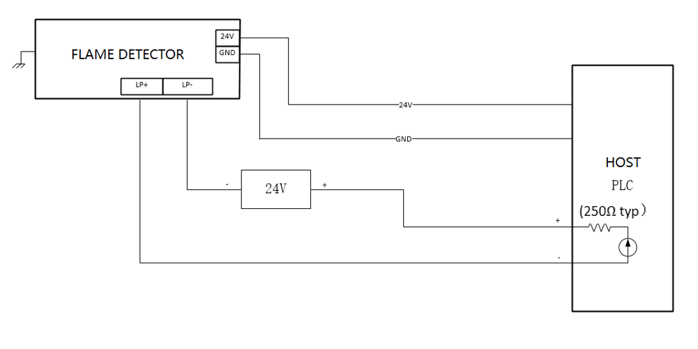
| 11 | +24V | DC 24V power input, polarity-free |
| 12 | GND | DC 2 4V power input, polarity-free |
| 13 | L2 | NA |
| 14 | L1 | NA |
| 15 | NC | Empty pin |
| 16 | 485_A | RS 485 bus A, RS485 + |
| 17 | 485_B | RS485 bus B, RS485- |
| 18 | LP+ | 4-20m A current loop + |
| 19 | LP- | 4-20mA current loop- |


| Fault Phenomenon | Cause Analysis | Solutions |
| The patrol light is off, and fault is reported | 1. The power cord is not connected | Check and connect the power cable |
| 2. Poor contact | Rewire | |
| 3. Wiring error | Check and connect the cable correctly according to the wiring diagram of the terminals | |
| No output signal after flame detector alarms | 1. The output cable is not connected properly | Check the output cable and connect it correctly according to the wiring diagram |
| 2. The output cable is wear off or open | ||
| Flame detector frequently reports false alarms after powered-on | 1. On-site environmental impact | Clear the interference sources in surrounding environment |
| 2. There is problem with the sensitivity setting | Adjust the sensitivity according to the actual situation on site |
| JTG-Z-JBF4386-Ex flame detector | ×1 |
| Manual | ×1 |
| Installation bracket | ×2 |
| Accessory: Inner hexagonal cylindrical head screw M16×35 ×1 (Used to connect product and installation brackets) Inner hexagonal cylindrical head screw M10×16 ×2 (Used to fix the installation brackets) Inner hexagonal flat head screw M6×8 ×1 (Used to fix the installation brackets) Spring washer 16 ×1 (Used to fix the installation brackets with the product) Flat washer 16 ×1 (Used to fix the installation brackets with the product) 10PIN terminal block ×1 (Used to output / provide power to external devices) 9PIN terminal block ×1 (Used to output / provide power to external devices) | ×1 |