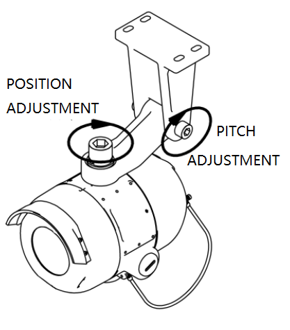
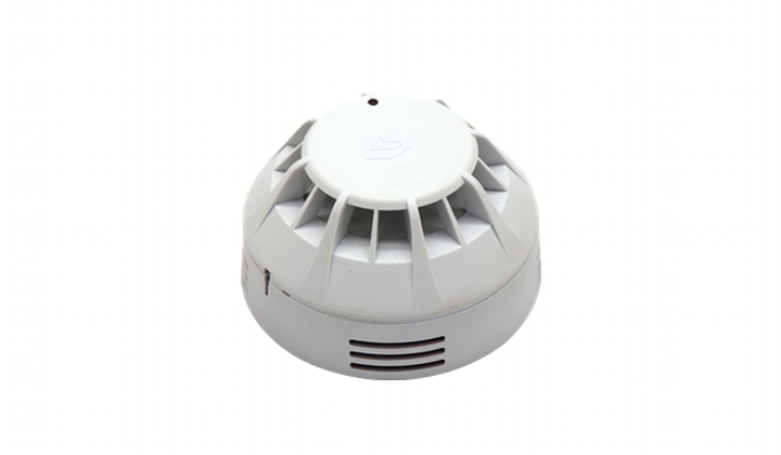
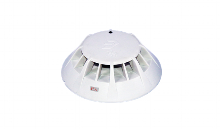
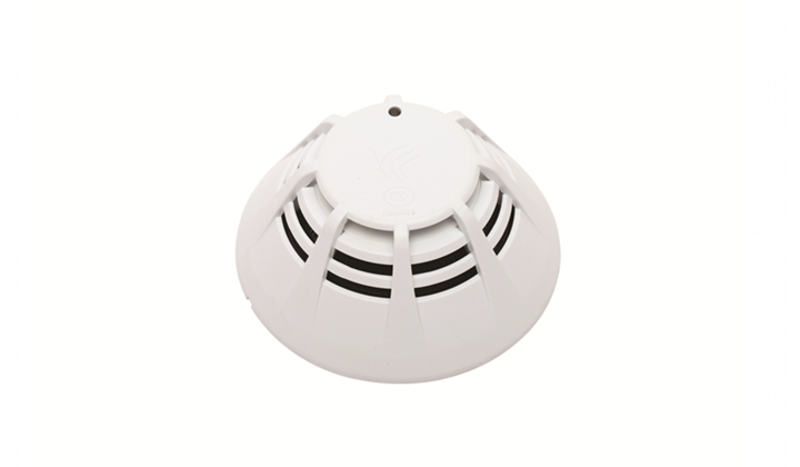
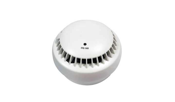
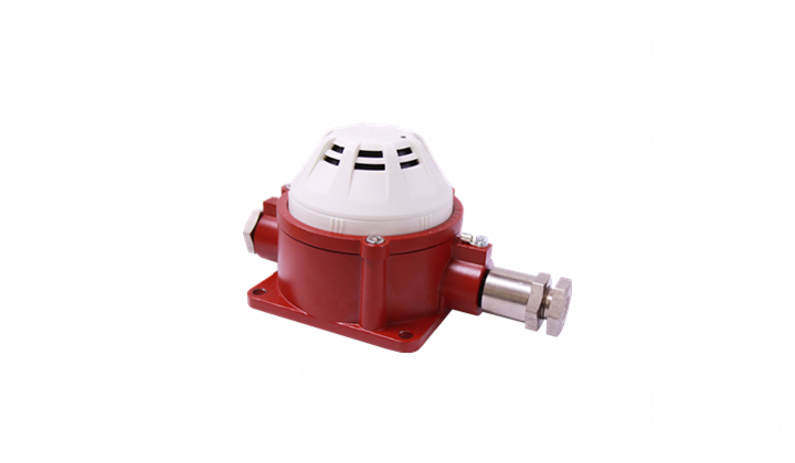
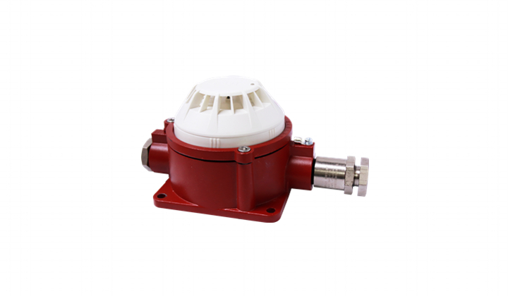
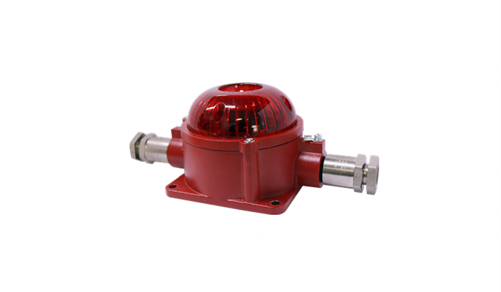
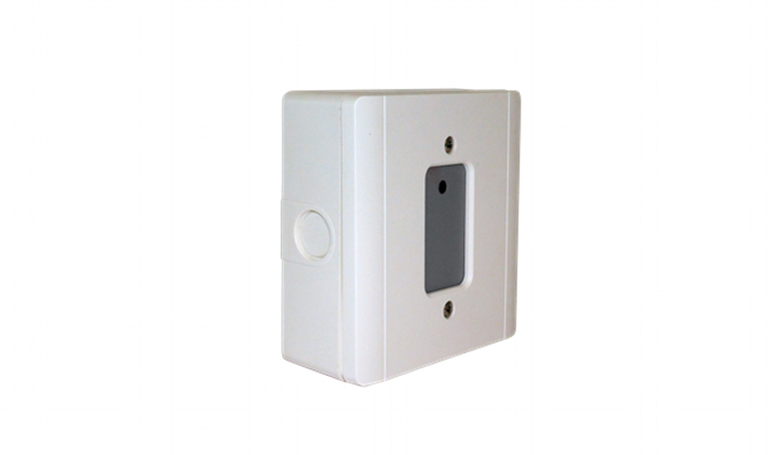
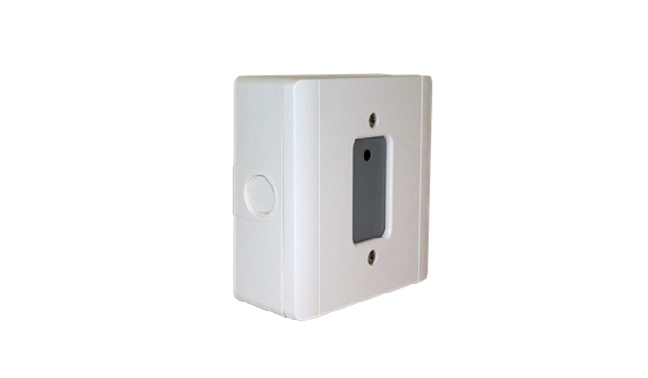
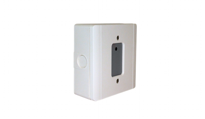
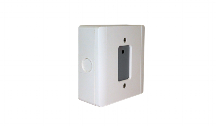
JTG-H-JBF4384-Ex point-type infrared flame detector (hereinafter referred to as flame detector), using a specially designed four-channel infrared sensor, and then through the built-in high-speed microprocessor and advanced signal processing algorithm, can effectively distinguish the true flame radiation from the interference sources, while increasing the alarm speed, greatly reducing the impact of environmental factors on the flame detector. The flame detector can be set with multiple levels of sensitivity to meet the needs of different occasions. Excellent flameproof and protective design ensures it apply to various harsh industrial environments.
Product Features- The product is designed according to the requirements of industry standards, and the performance is stable and reliable.
- The core circuit adopts SMT technology, which has high reliability and good consistency.
- Three-color indicator can display normal working status, alarm and fault status.
- Multi-level sensitivity is adjustable.
- Intelligent algorithm can not only realize fast alarm but also reduce false alarm rate.
- Fault mode can accurately locate the fault information.
- Automatic defrost function, better resistance to window condensation and frost in low temperature.
- Supports self-checking of the light path, which automatically carries out the same test conducted by the maintenance personnel with test lamps, ensuring reliable detection of the fire.
- Various output ports meet different application scenarios.
- Enclosure adopts High-strength die-cast aluminum and sapphire glass of high quality. Explosion-proof and the protection grade reaches IP67, with anti-dust, anti-moisture and the corrosion resistance characteristics.
- Explosion -proof performance complies with GB 3836.1-2010 Explosive atmospheres - Part 1: Equipment-General requirements, GB 3836.2-2010 Explosive atmospheres - Part 2: Equipment protection by flameproof enclosures “d”, GB 12476.1-2013 “Electrical apparatus for use in the presence of combustible dust - Part 1: General requirements”, GB 12476.5-2013 Electrical apparatus for use in the presence of combustible dust - Part 5: Protection by enclosures "tD"". The explosion-proof mark is Exd II.C T6 Gb/ExtDA21 IP67 T80C, and is suitable for hazardous sites in Area 1, Area 2, Area 21 and Area 22 that containing explosive mixtures of flammable gases in group T1 to T6, grades of A, B, C in category II, or dust and air. The relevant technical information, drawings and prototypes passed inspection by Supervision & Test Center of Ex-products of China Petroleum & Chemical Industry (PCEC) for electrical products.
- The flame detector has excellent anti-interference ability, and is not affected by wind and rain, high temperature, high humidity, natural artificial light source, lightning, etc., and can work well in various harsh industrial sites indoors or outdoors.
Technical Data
| Content | Technical Parameters |
| Electrical characteristics |
| Rated voltage | DC24V |
| Working voltage range | D C18 ~30V |
| Monitor current | 17mA ~ 27mA (D C24V ) |
| Alarm current | 28mA ~ 40mA ( D C24V ) |
| Heating current | 130mA ~ 220mA (D C24V ) |
| Power-on start time | 30sec. ( System self-check) |
| Relay contact capacity | 2A @ 30VDC |
| Mechanical properties |
| Appearance | R AL3001 signal red |
| Material | Die-casting aluminum |
| Electrical port | 3 × M20 × 1.5mm |
| Protection grade | IP67 |
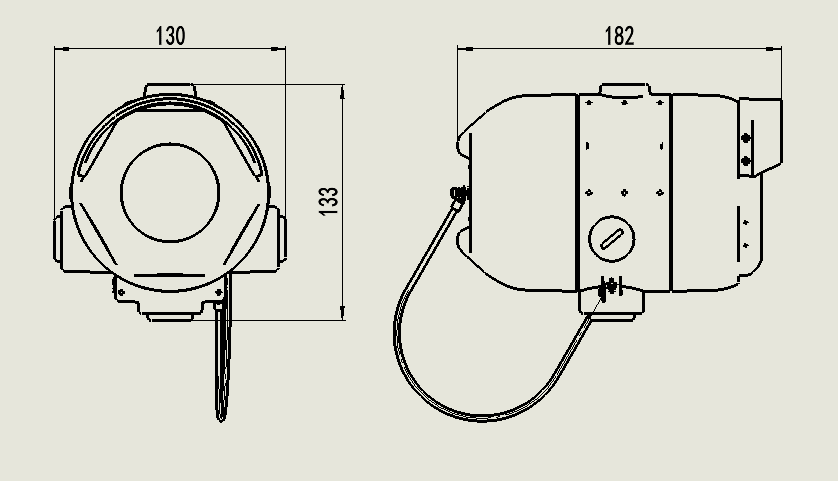
| Dimensions | L 133 mm × W 130 mm × H 182 mm (without mounting bracket) |
| Weight | 2.5kg (including mounting bracket) |
| Environmental characteristics |
| Ambient temperature | -40 ~+ 75 ℃ |
| Relative humidity | ≤ 95% (no condensation) |
| Storage temperature | -40 ~+85 ℃ |
| Explosion-proof characteristics |
| Explosion-proof mark | Exd II C T6 Gb / ExtDA21 IP67 T80 ℃ |
| Applied places | Applicable to various flammable and explosive industry (non-residential) sites: Area 1, Area 2, Area 21 and Area 22 that have explosion-proof requirements. |
| Applied standard |
| Applied standard | 15631-2008 GB , GB 3836.1-2010 , GB 3836.2-2010 ,
GB 12476.1-2013 , GB 12476.5-2013 |
Field of view ≤ 120 °; Sensitivity level: I (under standard test conditions, detection distance ≥ 25m)
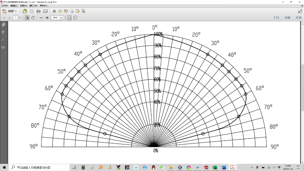
Schematic diagram of detection area
Structure and Installation Warning: Before installing the flame detector, be sure to cut off the power supply of the flame detector power supply line.
Note: During the on-site installation, according to the requirements of GB / T 3836.15-2017, the cable entry device and the explosion-proof plug must have obtained the explosion-proof certification that are suitable for the environment, and the cables must be high-temperature resistant.
Note: When the flame detector is installed in the explosion-proof zone, the connection should be of power limitation and controlled. The settings of the flame detector should follow "Code for design of automatic fire alarm system" (GB 50116).
Note: All wires used should be of 1.0 mm
2 or more. The end of the wire is stripped off about 6 mm of the insulating sheath, and connected to the terminals of JTG-H-JBF4384-Ex flame detector.
Note: Check whether the external connection line is open or short-circuited.
| Serial number | Name | Description |
| 1 | FIRNO | Normally open relay; the contact is closed when the flame detector reports fire alarm |
| 2 | FIRCOM | Common terminal of fire alarm relay |
| 3 | FIRNC | Normally closed relay; the contact is open when the flame detector reports fire alarm |
| 4 | FLTNO | Normally open relay; the contact is closed when powered on. The contact is open when the detector has fault. If the detector reports fire alarm at this time, the contact remains open. |
| 5 | FLTCOM | Common terminal of fault relay |
| 6 | FLTNC | Normally closed relay; the contact is open when powered on. The contact is closed when the detector has fault. If the detector reports fire at this time, the contact remains closed |
| 7 | AUXNO | Auxiliary relay, normally open, contact closed when flame detector reports fire. 1 |
| 8 | AUXCOM | Common terminal of auxiliary relay 1 |
| 9 | AUXNC | Normally closed auxiliary relay; the contact is disconnected when the flame detector reports fire. 1 |
| 1 0 | NC | Empty pin |
| 1 1 | +24V | DC 24V power input, polarity-free |
| 1 2 | GND | DC 2 4V power input, polarity-free |
| 1 3 | L2 | Fire bus loop L 2 , polarity-free |
| 14 | L1 | Fire bus loop L 1 , polarity-free |
| 15 | NC | Empty pin |
| 16 | 485_A | RS 485 bus A, RS485 +, used to configure flame detector |
| 17 | 485_ B | RS485 bus B, RS485- , used to configure flame detector |
| 18 | LP + | 4-20m A current loop + |
| 19 | LP- | 4-20mA current loop- |
Note 1 : The auxiliary relay is connected according to the actual needs of customers, and it can provide voltage-free normally open / normally closed contacts with the capacity of 2A@30VDC . External devices or loads should not exceed the contact capacity of the auxiliary relay.
JTG-H-JBF4384-Ex point type infrared flame detector and JB fire alarm control panel JB-QB- JBF5010 connection diagram
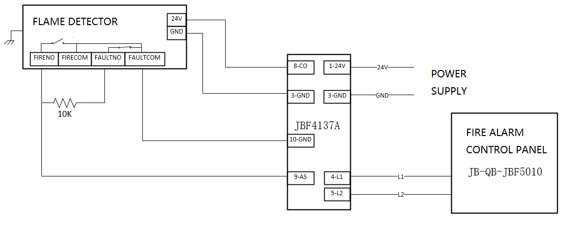
Wiring diagram of JTG-H-JBF4384-Ex point type infrared flame detector and PLC industrial computer
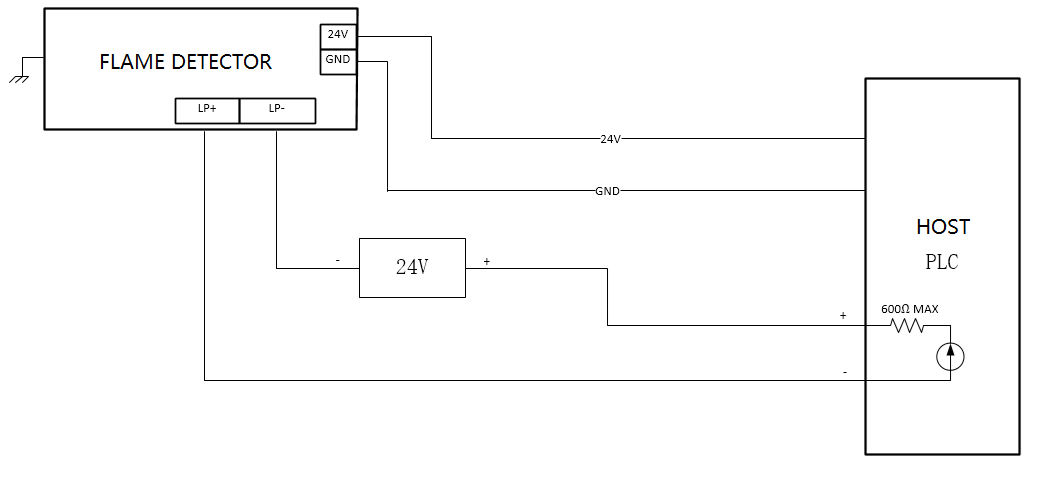
Note: Explosion-proof cable, lead-in devices and plugs must be provided, and their explosion-proof level must meet the requirements of Exd Ⅱ C T6 Gb / ExtDA21 IP67 T80 ℃ .
Precautions The internal and external grounding must be reliable.
After passing the inspection of qualified products, it is not allowed to replace components or change the structure at will, so as not to affect the explosion-proof performance.
During maintenance, pay attention to the explosion-proof surface. All explosion-proof surfaces must not be damaged or corroded.
It is strictly forbidden to open the cover while electrified.
Non-professionals are not allowed to install or disassemble the product.
Flame detectors must be regularly tested and maintained in accordance with national standards and relevant regulations. The detector must be cleaned at least once a year, and tested and maintained once a month.
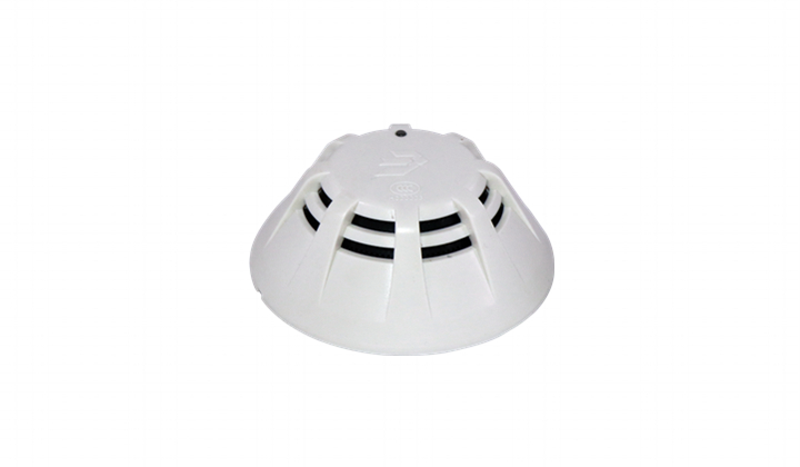

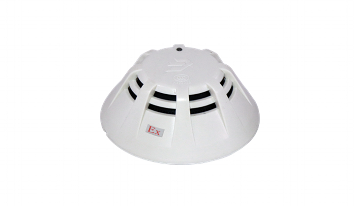
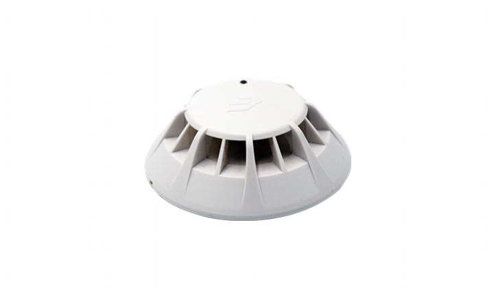












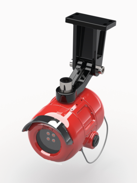




















 JTG-H-JBF4384-Ex point-type infrared flame detector (hereinafter referred to as flame detector), using a specially designed four-channel infrared sensor, and then through the built-in high-speed microprocessor and advanced signal processing algorithm, can effectively distinguish the true flame radiation from the interference sources, while increasing the alarm speed, greatly reducing the impact of environmental factors on the flame detector. The flame detector can be set with multiple levels of sensitivity to meet the needs of different occasions. Excellent flameproof and protective design ensures it apply to various harsh industrial environments.

