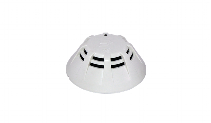
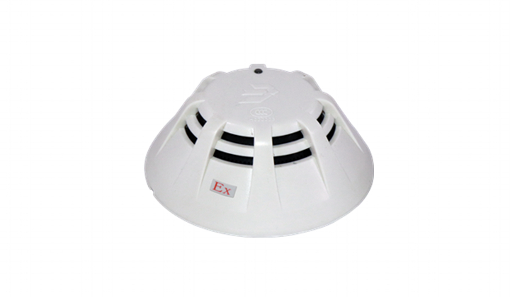
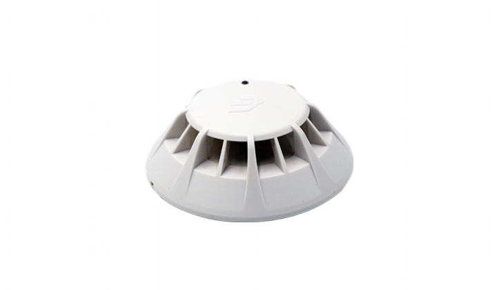
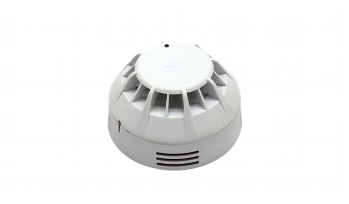
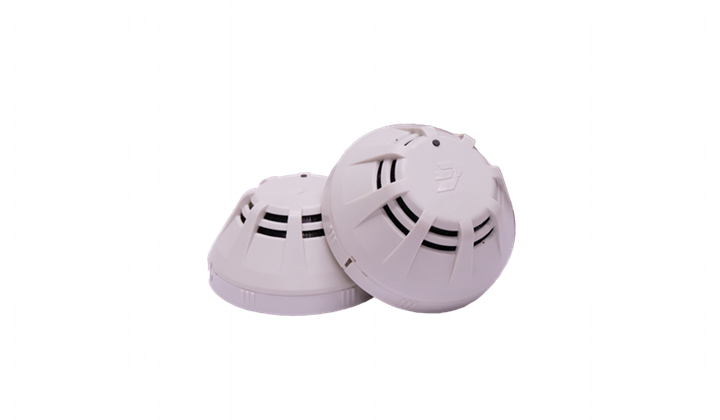
JBE-2111
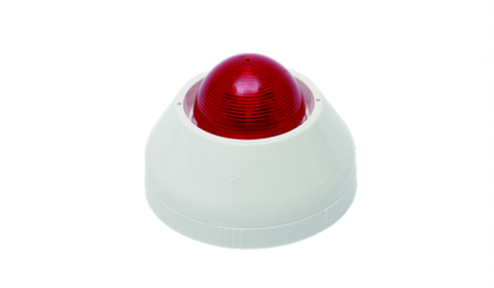
Applied to EN standard, dust compensation mechanism, extended output of 3~5mA current. External indicator can be lit when fire is reported

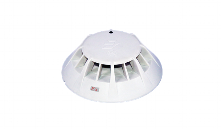
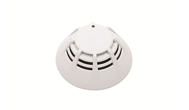
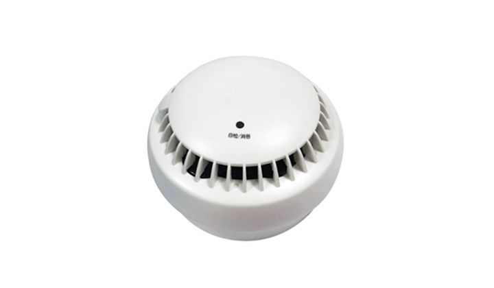

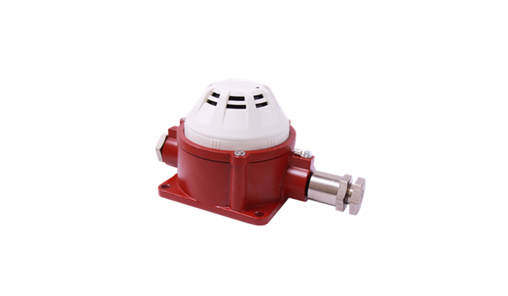
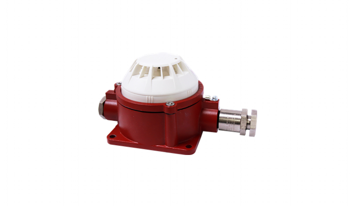
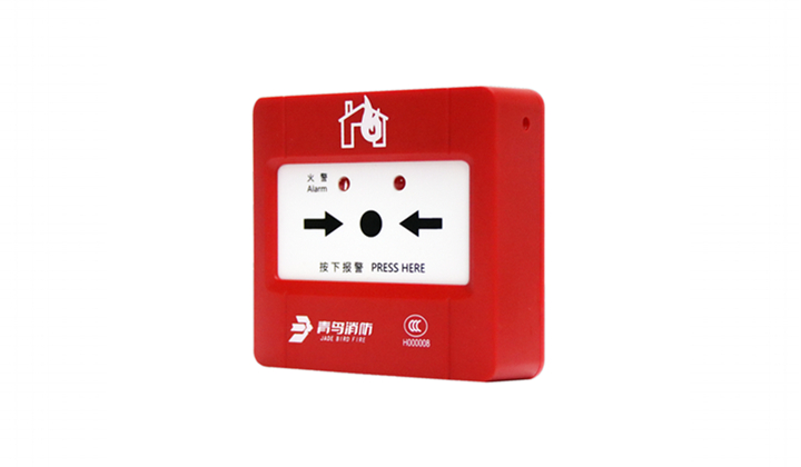

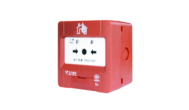

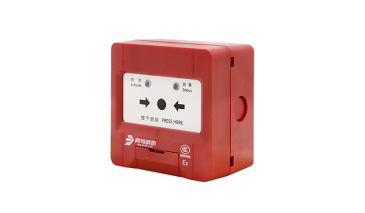













| Category | EN54-7 |
| Working voltage | DC 16 - 30 V (JBE protocol pulse amplitude) |
| Connection | 2-wire JBE communication bus, no polarity |
| Wiring | Twisted pair, max. wiring gauge 2.5 mm2 |
| Quiescent current | ≤0.3mA @24V |
| Activation current | ≤1mA @24V (plus <8 mA to remote indicator) |
| Working temp | -10~+60℃ |
| Storage temp | -30~+70℃ |
| Environment | ≤ 95% RH (40±2℃) (no condensation nor icing) |
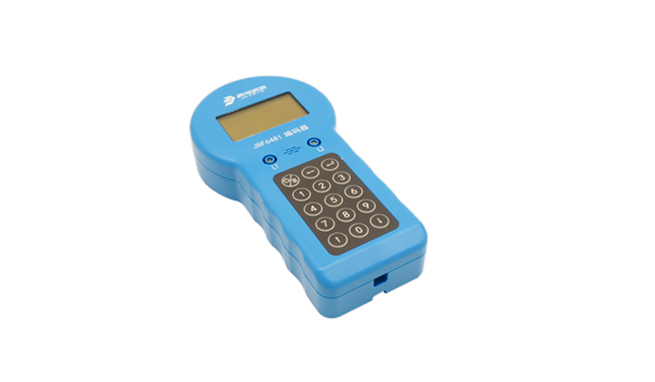
| Addressing method | Soft addressing with tool JBE-AT1, non-volatile |
| Address range | 1-200 |
| Protection area | 60~80m2 (subject to local codes) |
| Red LED indication | Flashes when polling Constant on when alarms |
| Dimension | 100mm × 46mm |
| Weight | 0.1 kg |
| IP rating | IP40 |
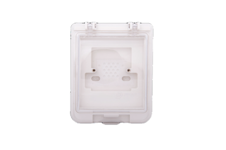
| Compatible bases | JBE-2160 for installation without remote indicator JBE-2165 for installation with remote indicator |
| Standards | En 54-7:2018 |
| Declaration of Perf. | DoP-0370-CPR-3808-1 |
| Profile 1 | EN54-7, earliest detection |
| Profile 2 | EN54-7, standard sensitivity |
| Profile 3 | EN54-7, strong false alarm rejection |

| Terminals | Connection |
| 1 & 2 | Signal loop L1, L2(no polarity) |
| 3 | Remote indicator negative (optional) |
| 4 | Remote indicator positive (optional) |
